


5.1
Hardware
5
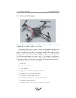
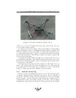
QUADROTOR PROTOTYPE CONSTRUCTION
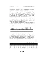
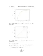
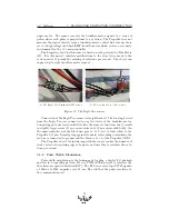
Figure 6: PWM vs RPM under no load. They are nearly the same on the PWM
up and down.
Figure 7: Volts vs RPM under no load. As you can see that the current is linear
with the voltage.
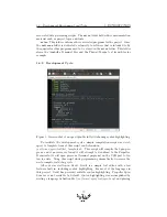
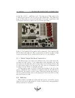
5.1.3
Power Board PCB
For this project we developed a custom circuit board to power the quadrotor.
This PCB has all the hardware on it to facilitate a number of features:
* Propeller microcontroller, overclockable
20


