Autometers Systems A-400 Series Скачать руководство пользователя страница 7

www.autometers.co.uk

6

4. Set Up

To enter set-up mode, press the           button for 3 seconds until the password screen appears.

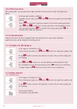
4.1 Set-up Entry Methods

Some menu items, such as password and CT, require a four-digit number entry while 

others, such as supply system, require selection from a number of menu options.

4.1.1 Menu Option Selection

Use the           and           buttons to scroll through the different options of the set-up menu.
Press          to confirm your selection.
If an item flashes, then it can be adjusted by the           and           buttons.
Having selected an option from the current layer, press          to confirm your selection. The 

SET indicator will appear.
Having completed a parameter setting, press          to return to a higher menu level. The 
SET indicator will be removed and you will be able to use the           and           buttons for 

further menu selection.

On completion of all setting-up, press           repeatedly until the measurement screen is 

restored.

The current digit to be set flashes and is set using the           and           buttons.
Press          to confirm each digit setting. The SET indicator appears after the last digit has 

been set.
After setting the last digit, press          to exit the number setting routine. The SET indicator 
will be removed.

Setting up is password-protected so you must enter the correct password 

(default ‘1000’) before processing.

If an incorrect password is entered, the display will show:
PASS  Err

To exit set-up mode, press the           button repeatedly until the measurement screen is restored.

When Setting up the unit, some screens require the entering of a number. In particular, 

on entry to the setting up section, a password must be entered. Digits are set individually, 

from left to right. The procedure is as follows:

4.1.2 Number Entry Procedure

E

V/A

ESC

V/A

ESC

V/A

ESC

V/A

ESC

MD/

PF/HZ

P

MD/

PF/HZ

P

MD/

PF/HZ

P

MD/

PF/HZ

P

E

E

E

Содержание A-400 Series

Страница 1: ...T MID Approved SGS UK Appendix B and D Measures kWh KVArh KVar PF Hz Max demand RS 485 Modbus Autometers V6 protocol Two Pulse Outputs BI Directional Measurement for Import and Export Back light LCD for full viewing Angles Available as 1 Phase 2 Wire 3 Phase 3 Wire and 3 Phase 4 Wire ...

Страница 2: ...of the meter The meters can also be supplied with different communication outputs Modbus RS 485 MBus or two individual Pulse outputs one programmable Declaration of Conformity We Autometers Systems Ltd 4B Albany Road Manchester M21 0AW UK ensure and declare that apparatus Energy Meter A 400P A 400M A 400MB A 400MT with the measurement range 3x230 400V 0 25 5 45 A 50Hz are in conformity with the typ...

Страница 3: ... monitoring and controlling the Unit screens are provided for setting up the RS485 port Set up screens are provided for setting up the M Bus port 1 4 Pulse output Two pulse outputs that pulse measured active and reactive energy The constant of pulse output 2 for active energy is 400imp kWh unconfigurable its width is fixed at 100ms The default constant of configurable pulse output 1 is 400imp kWh def...

Страница 4: ... display active energy measurements www autometers co uk 3 3 Keys and Displays 3 1 Button Functions Click Selects the Voltage and Current display screens In Set up Mode this is the Left or Back button Select the Frequency and Power factor display screens In Set up Mode this is the Up button Select the Power display screens In Set up Mode this is the Down button Select the Energy display screens In...

Страница 5: ...uccessive press of the button selects a new range Phase to neutral voltages Current on each phase Phase to neutral voltage THD of 2nd to 19th Each phase Current THD of 2nd to 19th Frequency and Power Factor total Power Factor of each phase Maximum Power Demand Maximum Current Demand Instantaneous Active Power in kW Instantaneous Reactive Power in kVAr Instantaneous Volt Amps in KVA Total kW kVArh ...

Страница 6: ...n 2000 default For A 400MT only Time Hour minute second Example 00 02 16 For A 400MT only Tariff 1 active energy Tariff 2 active energy Tariff 3 active energy Tariff 4 active energy For A 400MT only Imported reactive energy in kVArh Exported reactive energy in kVArh Tariff 1 reactive energy Tariff 2 reactive energy Tariff 3 reactive energy Tariff 4 reactive energy For A 400MT only The parameters of date a...

Страница 7: ...ther menu selection On completion of all setting up press repeatedly until the measurement screen is restored The current digit to be set flashes and is set using the and buttons Press to confirm each digit setting The SET indicator appears after the last digit has been set After setting the last digit press to exit the number setting routine The SET indicator will be removed Setting up is password ...

Страница 8: ...pear Press to exit the DIT selection routine and return to the menu Use and to set the first digit and press to confirm your selection The next digit will flash Repeat the procedure for the remaining three digits After setting the last digit SET will show Press to exit the number setting routine and return to the set up menu SET will be removed www autometers co uk 7 This sets the period in minutes o...

Страница 9: ...er pulse Use and buttons to choose pulse rate On completion of the entry procedure press to confirm the setting and press to return to the main set up menu Press to enter the selection routine The unit symbol will flash Use and buttons to choose kWh or kVArh On completion of the entry procedure press to confirm the setting and press to return to the main set up menu 4 5 Supply System The unit has a d...

Страница 10: ... Use and buttons to choose pulse rate On completion of the entry procedure press to confirm the setting and press to return to the main set up menu 4 6 2 Pulse Duration 4 7 Communication The pulse width can be selected as 200 non MID version meters only 100 default or 60ms Where the meter has been supplied with a Rs 485 protocol output the individual parameters are set by using the front key panel ...

Страница 11: ...ity 4 7 5 Stop Bits From the set up menu use and buttons to select the Baud Rate option Press to enter the selection routine The current setting will flash From the set up menu use and buttons to select the Parity option Press to enter the selection routine The current setting will flash Press to enter the selection routine The current setting will flash From the set up menu use and buttons to select...

Страница 12: ...ed Exported reactive energy Total active energy Total reactive energy 5 2 Measured Inputs 2 Voltage inputs through 4 way fixed connector with 25mm stranded wire capacity single phase two wire 1 p2w three phase three wire 3p3w or three phase four wire 3p4w unbalanced Line frequency measured from L 1 voltage or L3 voltage 5 3 Interfaces for External Monitoring Three interfaces are provided RS 485 com...

Страница 13: ...D Response time to step input 5 5 Reference Conditions of Influence Quantities Influence Quantities are variables that affect measurement errors to a minor degree Accuracy is verified under nominal value within the specified tolerance of these conditions Ambient temperature Input waveform Input waveform 5 6 Environment Operating temperature Storage temperature Relative humidity Altitude Warm up time Vi...

Страница 14: ...ormation before attempting installation or other procedures Symbols used in this document Risk of Danger These instructions contain important safety information Read them before starting installation or servicing of the equipment Caution Risk of Electric Shock 7 Wiring Diagrams www autometers co uk 13 72 x 100 mm WxH per DIN 43880 DIN rail DIN 43880 Ip51 indoor Self extinguishing Ul94 V 0 B TX A T...

Страница 15: ...L1 L2 L3 N 1 2 3 4 5 6 7 8 L1 L2 L3 L1 L2 L3 1 2 3 4 5 6 7 8 L1 N L1 N 1 2 3 4 5 6 7 8 L1 L2 L3 L1 L2 L3 1 2 3 4 5 6 7 8 L1 N L1 N 1 2 3 4 5 6 7 8 The A 400 can be supplied with two wiring configurations Mains entering at the top load at the bottom see fig A or mains entering at the bottom load at the top see fig B MAINS LOAD MAINS LOAD Fig A Mains at the top Fig B Mains at the bottom ...

Страница 16: ...tice Products as delivered may therefor differ from the descriptions and illustrations in this publication VOLTAGE 3X230 400V CURRENT 0 25 5 6 A FREQUENCY 50Hz COMMS RS 485 Modbus RTU BAUDRATE 2400 38400BPS INSTALLATION CAT III IC 1095 www autometers co uk Communications shield continuous Communications Shield Belden 9841 or Equal Cable Screened Twisted pair with full Coax shielding for RS 485 Modb...

Отзывы: