7
www.automationdirect.com/click-plc
3505 HUTCHINSON ROAD
CUMMING, GA 30040-5860
1-800-633-0405
C2-03CPU Quick Start Guide
Copyright© 2020,
Automationdirect.com
Incorporated/All Rights Reserved Worldwide
External Features
CPU is shown with op�onal C2-FILL Op�on Slot Cover installed.
Mode
S
W
S
t
a
t
us LED
s
mic
ro US
B
O
p
�o
n
Sl
ot
(f
or O
p
�on Sl
ot
Module
)
(Device)
(10/100)
E
t
herne
t
Serial
P
or
t
R
S-232
Serial
P
or
t
R
S-
485
Ex
p
a
nsion
Conn
ec
to
r
W
LAN/BLE Ex
t
ernal A
nt
enna Port
Pow
er
Block
T
er
min
al
B
a�er
y
(
O
p
�on
)
Mic
ro SD-Card
C2-03CPU
Blink
LNK/ACT LED (Green)
On Connected to the network
Communicating
Disconnected from the network
Off
100MBIT LED (Orange)
On
Communicating at 100Mbps
Communicating at 10Mbps or
disconnected from the network
Off
TX & RX LED (Green)
On Com Port Data Active
No Communication
Off
ERROR LED (RED)
On
Self Diagnostic
Error
Self Diagnostic
Warning
No Error
Off
Blink
WLAN LED (Green)
On
Link
Activity
No Link
Off
Blink
MICRO SD LED (Green)
On
Mounted
Access
No SD Mounted
Off
Blink
POWER LED (Green)
On Power Good
USB Low
Power Mode
Power Failure
Off
Blink
BLUETOOTH LED (Blue)
On
Link
Activity (per packet)
Blink
Disabled in PLC
(200ms flash)
No Link
Off
Blink
Pairing Mode
(500ms flash)
Blink
RUN LED (Green)
On CPU Run Mode
Initializing
Analog Module
CPU Program
Mode
Off
Blink
LED Status Indicators
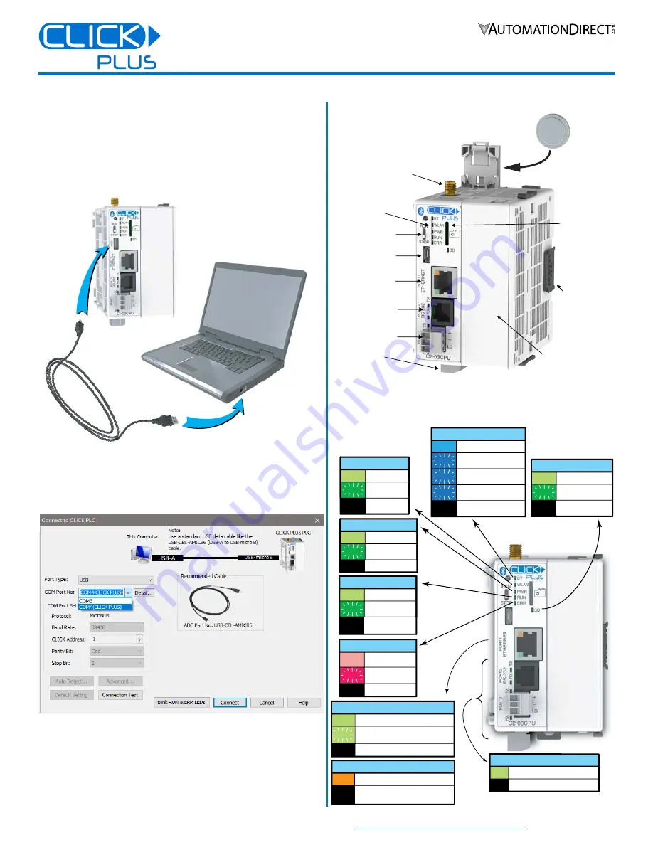
Connecting via USB
To connect the CLICK PLUS CPU to a PC, use a USB A
to USB micro-B cable, such as the AutomationDirect
USB-CBL-AMICB6 cable.
1.
Connect the cable between the CPU micro-B port and an
available USB port on your PC.
USB Cable
ADC Part #
USB-CBL-AMICB6
PC with
USB A Port
USB B
Port
CLICK Plus
PLC
2.
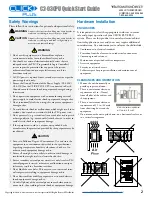
Once connected open the Software and select the PLC Menu
and Connect.
3.
In the Connect to PLC Window, select USB for Port Type.
4.
For Com Port No., select the COMX (CLICK PLUS).
LOAD A PROJECT
The CLICK PLUS CPU is now ready to continue
configuration using the CLICK software and load a project.


