


RHINO Battery Control Module PSM24-BCM360S Operating Instructions
4th Edition 06/18
1 - 8 0 0 - 6 3 3 - 0 4 0 5
4
10. Now the PSM Power Supply will switch on the BCM and the UPS system is operational.
11. The potentiometer on the BCM is set by the factory to suit Valve Regulated Lead Acid Battery from Panasonic and equivalent types (the recommended
battery type) and should not be adjusted by the user, unless other Lead Acid Batteries of different voltage temperature characteristics are connected.
12. If a non recommended battery is applied to the circuit, the output voltage of the BCM module needs to be adjusted to a different “End of Charge
Voltage.” This voltage value can be obtained from battery manufacturer’s datasheets.
13. The Temperature Sensor should now be fixed to the battery and connected to J5 on the BCM
14. Next the battery wires should be connected on the BCM module;
DO NOT connect to the battery first
.
15. Then connect the battery wires on the battery.
16. Next the Load can be connected to J2 of the BCM.
17. To verify proper functionality, switch off the input AC power at the external circuit breaker and output power should be supplied from the battery if a
fully charged battery has been connected.
18. For proper operation, a new system should always start up with a fully charged battery. If a fully charged battery is not connected, the battery should
be charged in full over night before any load is applied to the output of the BCM module.
19. The system is now fully operational and the output load can be connected.
DC-Input (Connector J1, pin 1 & pin 2)
Make the 24 VDC connection using the –Vin (–DC In) and +Vin (+DC In) connections following all local regulations. Properly
sized wiring must be used. To achieve a reliable and shockproof connection, strip the connecting ends according to the table below.
If flexible wires are used, terminate them using ferrules.
Battery In (Connector J1, pin 3 and pin 4)
Make the battery connection using the “+Bat In” and “–Bat In” connections.
Make sure that the battery lines are sized according to
the maximum output current (see Connections and Terminal Assignments table below) or are separately protected.
The wires on the
secondary side should have large cross sections to keep the voltage drops on these lines as low as possible. To achieve a reliable and
shockproof connection, strip the connecting ends according to table below. If flexible wires are used, terminate them using ferrules.
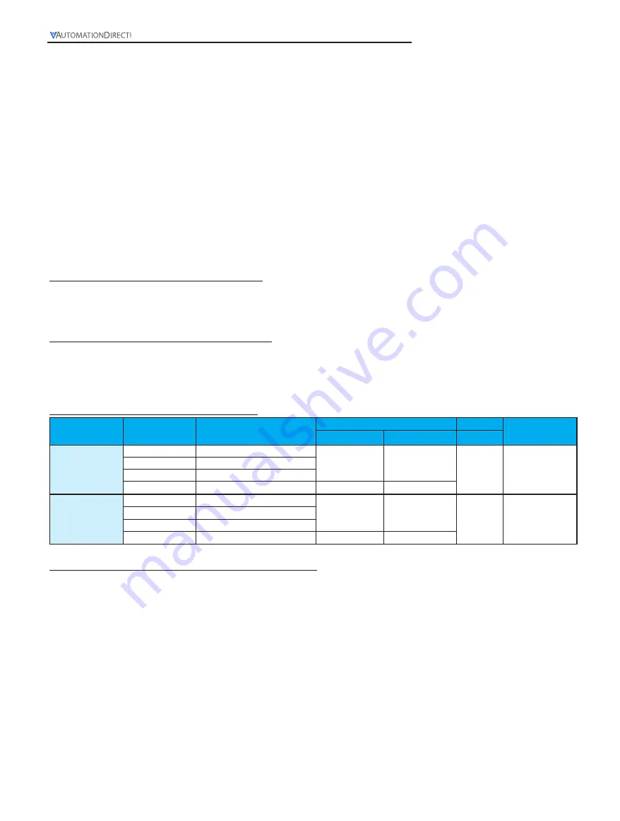
Connections and Terminal Assignments
Device
Terminals
Function
Solid or Stranded Wires
Torque
Stripping
Length, mm
mm
2
AWG
Nm
PSM24-090S
PSM24-180S
+Vin & - Vin
Input voltage (24 VDC)
0.5 to 2.5
24 to 12
0.5 to 0.6
7.0
+Bat & - Bat
Battery voltage (24 VDC)
+Vout & - Vout
Output voltage (24 VDC)
Signal
Relay inputs and relay outputs
0.2 to 2.5
32 to 12
PSM24-360S
+Vin & - Vin
Input voltage (24 VDC)
1.0 to 2.5
18 to 12
0.5 to 0.6
7.0
+Bat & - Bat
Battery voltage (24 VDC)
+Vout & - Vout
Output voltage (24 VDC)
Signal
Relay inputs and relay outputs
0.2 to 2.5
32 to 12
Output (Connector J2, pin 1, pin 2, pin 3 & pin 4)
The 24VDC connection is made using the “+Vout” and “–Vout” terminals. All output terminals should be connected to the load.
Make sure that all output lines are sized according to the maximum output current (see Connections and Terminal Assignments
table above) or are separately protected.
The wires on the secondary side should have large cross sections in order to keep the voltage
drops on these lines as low as possible.
To achieve a reliable and shockproof connection, strip the connecting ends according to the table above. If flexible wires are used,
terminate them using ferrules.
The device is protected against overload and short circuit.