


Owner Installation Instructions
GDO-9
17
10
0
Mounting Door Bracket & Arms
18
fi g
20
fi g
21
fi g
19
fi g
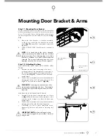
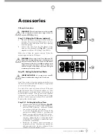
Step 11 - Mounting Door Bracket
The door bracket comes in two parts. The bottom plate
with two mounting holes is used on its own for one piece
doors. For sectional doors, the top plate is placed over
the bottom plate and is fi xed with four (4) screws
(Fig.
18).
Mount the door bracket, or bracket assembly,
on the door’s centre line one-third down the top
panel
(Fig. 18)
using M6 or equivalent screws (not
supplied),
STEEL DOORS ONLY: Bracket can be welded in
place.
NOTE:
If in doubt about the door’s strength,
reinforcement may be added to the door’s frame
where necessary. Door damage may occur if the
bracket is installed on a panel with insuffi cient
strength. The opener’s warranty does not cover
damage caused to the door and/or door panels.
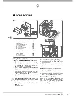
Step 12 - Attaching the Arms
FOR SECTIONAL AND ONE PIECE DOORS WITH
TRACK:
Assemble the bent arm(connecting to the door)
to the right side of the straight arm (connecting to
the shuttle) with bolts and nuts supplied in the ac-
cessory pack
(Fig. 19)
. Always use both bent and
straight arms.
Connect the assembled arm to the bracket and the
disengaged trolley with clevis and snap pins. The
angle “A” must be more than 10°
(Fig. 20)
.
WARNING:
Connecting the bent arm the other
way around may damage the door. The straight
arm should not protrude beyond the heel of the
bent arm.
FOR ONE PIECE DOORS WITHOUT TRACK
Assemble the bent and straight arms as shown
in
(Fig. 21)
with bolts and nuts supplied in the
accessory pack. Always use both the bent and
straight arms.
Connect the assembled arm to the bracket and the
disengaged trolley with clevis and snap pins.
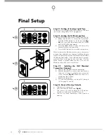
If installing on a door with a bad wave action,
lengthening the arm will assist in reducing this
effect.
IMPORTANT NOTE:
Adjust the length of the
cord so that its toggle is no more than 1.8m from
the ground.
a.
b.
a.
b.
a.
b.
c.
Arm connected to
the door
Arm connected to
the shuttle
A
Centre of the door
Содержание GDO-9 Dynamo Gen 2
Страница 9: ...Owner Installation Instructions GDO 9 9 01 17 16 15 14 08 06 02 03 04 05 07 09 10 11 12 13 01 fig ...
Страница 11: ...Owner Installation Instructions GDO 9 11 01 17 16 15 14 08 06 02 03 04 05 07 09 10 11 12 13 02 fig ...
Страница 33: ...Owner Installation Instructions GDO 9 33 Enduro Parts Listing 49 fig ...
Страница 34: ...34 GDO 9 Owner Installation Instructions Dynamo Parts Listing 50 fig ...


