20
Instructions for the installer
1
4
5
6
2
3
7
8
10
11
12
13
14
15
9
23
22
1
5
6
14
15
16
17
24
18
19
20
8
9
10
21
11
12
13
3
4
2
25
7
15
28
26
27
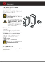
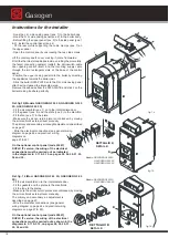
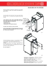
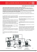
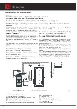
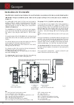
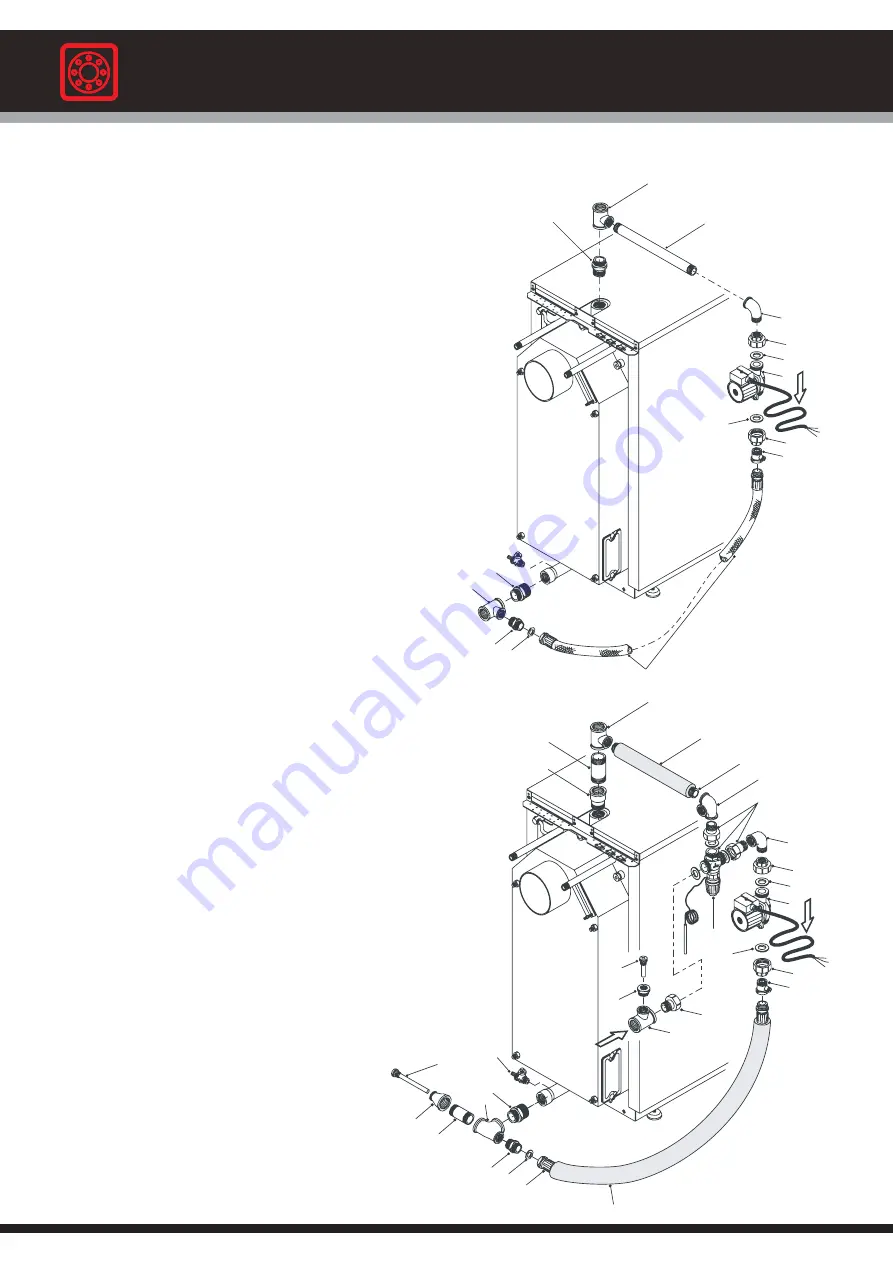
To ensure correct operation of the GASOGEN G3 2S boilers it
is necessary to fit a recirculation pump in order to avoid low
temperature water returns that could jeopardize the boiler’s
life span.
Automatic Heating, to favour her clients, has developed a water
recirculation kit that optimizes the water recirculation within
the boiler.
This kit is supplied separately as an option and is available, on
request, by indicating the appropriate part number .
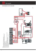
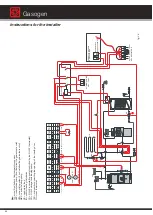
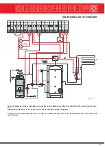
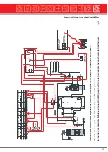
The pump’s electric connection must be carried out according
to the general wiring diagram shown on page 44 and the
practical wiring diagrams shown on page 21 & 22.
On the optional control panel (code 23557) DUPLO IT
version, the wiring of the electrical connections must be
carried out as shown in the diagrams in 3.11 & 3.12, on
pages 24, 26, 29, 31, 33, 36 and 39.
fig. 19
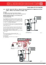
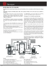
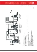
RECIRCULATION KIT FOR OPERATION WITH HOT WATER
STORAGE TANK (see 3.12 on page 27)
NOTE: For correct control of the storage tank, in addition
to fitting the recirculation kit, foreseen for this purpose,
the optional control panel code 23577 must be fitted.
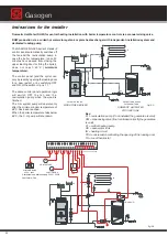
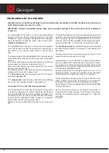
To ensure correct operation of the GASOGEN G3 2S boilers,
when a storage tank is used,
it is indispensable to install
the return sensor (Tr),
as shown in the diagrams in figs. 29,
31, 33, 35 and 37.
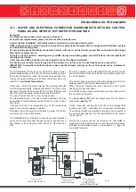
Automatic Heating has developed a RECIRCULATION KIT FOR
OPERATION WITH A STORAGE TANK.
This kit is supplied separately as an option and can be ordered
by indicating the code of your own boiler.
The return sensor (Tr) has to be inserted in the bulb holder
pos. 26, placed in the boiler C.H. return connection.
Please refer to the control panel’s instruction manual, in 5.5.7
“Return flow sensor installation” for the return sensor’s (Tr)
electrical connection and for any problems connected with it.
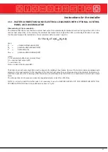
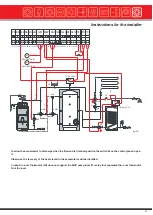
Note:
The “MAXP” function (heat discharge pump) will be
carried out by the “MKP” pump (central heating pump) (see
5.3 “Loads and sensors connection diagram”); then connect
the jumper 30-38.
On the optional control panel (code 23557)
DUPLO IT version, the wiring of the electrical
connections must be carried out as shown in the
diagrams in 3.11 & 3.12, on pages 24, 26,
29, 31, 33, 36 and 39.
fig. 20
Gasogen
Содержание Gasogen
Страница 1: ...Wood Fired Boiler Gasogen 29 93kW Installation and Servicing Manual ...
Страница 66: ...Gasogen notes ...
Страница 67: ...notes ...

