14
n
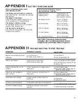
If the amount of voltage drop is at or below the amount
specified: that part of the circuit is functioning properly.
n
If the amount of voltage drop is above the amount
specified: move the leads progressively across each
section of the circuit until the defective section is found.
n
If the voltage level is within the specified levels: charging
system does not have resistance problems.
n
If voltage drop is more than the specified levels:
individually check each section of the charging system.
n
If drop exceeds maximum level, proceed to determine
which circuit may have a high resistance.
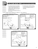
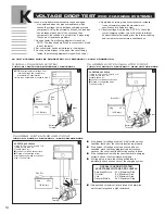
VOLTAGE DROP TEST
(FOR ChARGING SYSTEMS)
k
OvERALL ChARgINg SYSTEM
TURN VOLT SWITCh FROM INTERNAL TO EXTERNAL
24 VOLT SYSTEMS MUST BE CONNECTED TO A TEMPORARY 12 VOLT CONNECTION.
ChARgINg SYSTEM INSULATED CIRCUIT
TURN VOLT SWITCh TO EXTERNAL - READ VOLTAGE DROP
Loose or corroded terminal connections and damaged
or undersized wires can produce resistance, which
causes the voltage to drop between charging systems
components. Using the external volt leads, volt readings
can be taken of each part of the circuit and then
compared to the voltage of a normal circuit, pinpointing
the source of resistance problems.
1. Hook-up tester. See following diagrams for hook-up.
NOTE: The Inductive Amp Probe is connected to a load
lead of the tester.
2. Set volt selector switch as indicated in the diagram.
3. Hook-up external leads to the part of the circuit being
tested. (See following diagrams for specific hook-up.)
4. Apply load by turning load knob clockwise. Increase
load until ammeter reads the manufacturers
specification for alternator output.
5. Observe voltage drop reading. NOTE: To check the
overall charging system, turn volts switch to internal.
Subtract the external reading from the internal reading
and compare to manufacturers specifications.
Black
Black
Ext.
Ground
-
Neg
+
Pos
Red
Red
Ext.
12V Battery
Black
Black Ext.
-
Neg
+
Pos
Red
Red
Ext.
Battery
Terminal
Battery
Terminal
12V Battery
nOTE:
Subtract external voltage from
internal voltage and compare to
manufacture’s specification.
If more than acceptable, proceed to step 2.
Battery
Terminal
ChARgINg SYSTEM gROUND CIRCUIT
TURN VOLT SWITCh TO EXTERNAL - READ VOLTAGE DROP
Black
Black
Ext.
Ground
-
Neg
+
Pos
Red
Red Ext.
12V Battery
OVERALL CHARGInG SYSTEM
ACCEpTABLE VOLTAGE DROp LEVELS
American Motors .65 V. Maximum Drop
Chrysler
.9 V. Maximum Drop
Ford
.8 V. Maximum Drop
General Motors
.65 V. Maximum Drop
1
2
3
ACCEpTABLE LEVELS
If drop is .5V or less: Circuit Is O.K.
If drop is more than .5V...
Visually check for:
n
Loose or corroded connections.
n
Frayed or undersized wires.
Proceed to step 3.
ACCEpTABLE LEVELS
If drop is .5V or less: Circuit Is O.K.
If drop is more than .5V...
Visually check for:
n
Loose or corroded connections.
n
Frayed or undersized wires.
After repairs are made, proceed to
step 1 for final test.


