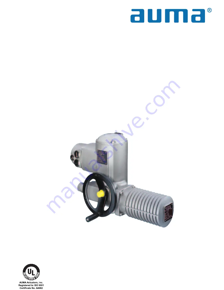
Electric part-turn actuators
Operation instructions
SG 05.1 – SG 12.1
SGR 05.1 – SGR 12.1
AUMA NORM
for flange type FA
Страница 1: ...Electric part turn actuators Operation instructions SG 05 1 SG 12 1 SGR 05 1 SGR 12 1 AUMA NORM for flange type FA...
Страница 2: ...t switching CLOSED 12 9 Setting the end stops for part turn actuators on ball valves 13 9 1 Setting end stop OPEN 13 9 2 Setting end stop CLOSED 13 9 3 Setting limit switching OPEN 13 10 Changing the...
Страница 3: ...onic position transmitter RWG option 21 17 1 Setting 2 wire system 4 20 mA and 3 4 wire system 0 20 mA 22 17 2 Setting 3 4 wire system 4 20 mA 23 18 Setting the mechanical position indicator 24 19 Clo...
Страница 4: ...may occur Check the surface temperature prior to contact in order to avoid burns The following references draw special attention to safety relevant proce dures in these operation instructions Each is...
Страница 5: ...imit and torque transmitter MWG only possible in combination with actuator controls AUMATIC Position feedback signal analogue options Potentiometer or 0 4 20 mA RWG For further details see separate da...
Страница 6: ...to 140 F with 3 phase AC motor Options 40 to 60 C 40 to 140 F low temperature 50 to 60 C 75 to 140 F extreme low temperature SG with 3 phase AC current only Lifetime SG 05 1 SG 07 1 20 000 operating c...
Страница 7: ...table corrosion protection agent to uncoated surfaces If part turn actuators are to be stored for a long time more than 6 months the following points must be observed additionally Prior to storage Pro...
Страница 8: ...ired The handwheel does not rotate during motor operation Turning the handwheel during motor operation results in an extension or reduction of the operating time depending on the direction of rotation...
Страница 9: ...A or B ensure that dimensions X Y and Z are observed refer to table 1 Apply non acidic grease at splines of coupling Fit actuator so that fixing holes in actuator and valve mounting flange are in alig...
Страница 10: ...mental influences is available 7 2 Delay time The delay time is the time from the tripping of the limit or torque switches to the motor power being removed To protect the valve and the actuator we rec...
Страница 11: ...switch If different potentials are to be switched simultaneously tandem switches are required To ensure correct actuator indicationss the leading contacts of the tandem switches must be used for that...
Страница 12: ...he stop In case end position CLOSED has been passed reverse several turns at the handwheel and approach end position again Turn end stop 10 by 1 8 turn counterclockwise Protective cap 16 must not be l...
Страница 13: ...up to the stop In case end position OPEN has been passed reverse several turns at the handwheel and approach end position OPEN again Turn end stop 10 by 1 8 turn clockwise Protective cap 16 must not...
Страница 14: ...4 with open end wrench 19 mm and fasten set screw 2 02 with torque 85 Nm Check O ring 016 and replace if damaged Replace protective cap 16 10 2 Reducing the swing angle Unscrew protective cap 16 figur...
Страница 15: ...by specially instructed personnel under the control and supervision of such an electrician and in accordance with the applicable electrical engineering rules 11 1 Removing the cover from the switch c...
Страница 16: ...il valve is open To prevent that the end stop is reached due to overrun before the limit switch has tripped turn handwheel 4 turns overrun in clockwise direction During test run check overrun and if n...
Страница 17: ...EN white section Move valve to desired intermediate position Press down and turn setting spindle K figure K 2 with a flat blade screw driver in direction of arrow while observing pointer L While a rat...
Страница 18: ...oad protection over full travel also when stopping in the end positions by limit switching 14 2 Checking the torque switches The red test buttons T and P figure K 1 are used for manual operation of th...
Страница 19: ...wrong switch off immediately Correct phase sequence at motor connection Repeat test run 15 2 Checking the limit switching Move actuator manually into both end positions of the valve Check whether limi...
Страница 20: ...2 back a little Due to the ratio of the reduction gearings for the position transmitter the complete resistance range is not always utilized for the whole travel Therefore an external possi bility for...
Страница 21: ...1 is located under the cover plate figure P 2 Part turn actuators SG 05 1 SG 12 1 SGR 05 1 SGR 12 1 Operation instructions AUMA NORM Terminal plans KMS TP_ _ 4 _ _ _ 3 or 4 wire system KMS TP _ 4 _ _...
Страница 22: ...urn potentiometer 0 clockwise until output current starts to increase Turn potentiometer 0 back until the following value is reached for 3 or 4 wire system approx 0 1 mA for 2 wire system approx 4 1 m...
Страница 23: ...l output current starts to increase Turn back potentiometer 0 until a residual current of approx 0 1 mA is reached Move valve to end position OPEN Set potentiometer max to end value 16 mA Move valve t...
Страница 24: ...indicator disc turns approx 180 for a swing angle of 90 19 Closing the switch compartment Clean sealing faces of housing and cover Check whether O ring is in good condition Apply a thin film of non a...
Страница 25: ...od condition Apply a thin film of non acidic grease to the sealing faces Fit and fasten motor cover For enclosure protection IP 68 the motor cover is additionally sealed with thread sealing material C...
Страница 26: ...f the cable glands must be suitable for the outside diameter of the cables refer to recommen dations of the cable gland manufacturers As standard actuators and controls are delivered without cable gla...
Страница 27: ...mportant that the O rings at the covers are placed correctly and cable glands tightened firmly to prevent ingress of dirt or water We recommend additionally If rarely operated perform a test run about...
Страница 28: ...s a rule these substances are hazardous to water and must not be released into the environment Arrange for controlled waste disposal of the disassembled material or for separate recycling according to...
Страница 29: ...bricant Temperature range auma CC AUMA ACTUATORS INC PITTSBURGH PA USA SG 07 1 F7 Com No 1309533 No 3302MD 19302 n 11 rpm T open 120 300Nm T close 120 300Nm Lubr F1 Temp 25 C 80 C 152 2 152 1 153 2 15...
Страница 30: ...assly 36 0 B Control unit assly without switches 36 1 B Torque switching head 36 2 B Heater 36 3 1 B Stud bolt for switches 36 3 2 B Switch for limit torque switching including pins at wires 36 3 4 E...
Страница 31: ...H Handwheel 8 Heater 11 I Indicator disc 24 L Limit switches 11 Limit switching 16 17 Lubrication 27 M Maintenance 4 Manual operation 8 Mechanical position indicator 24 Motor protection 11 Mounting t...
Страница 32: ...waukee Minneapolis Montana Monterrey Mexico New York Omaha Orlando Philadelphia Phoenix Pittsburgh Rochester Salt Lake City San Diego San Francisco San Juan Seattle St Louis Toronto Tulsa Internationa...