


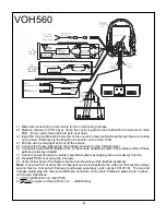
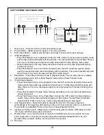


1) Make the connections to the vehicle for the 12 pin wiring harness.
2) Remove screws on PCB Cover. Open the cover to gain access to Mini-Din Connector on main
PCB. (Cover will remain attached at to rivet hole).
3) Insert the Circular Mini-Din Connector of the source Component Harness through the wire tie loop
on the main PCB and into the Mini-Din Connector on the main PCB.
4) Pull the wire tie loop tight and cut off the excess.
5) Connect the Power Harness to the mating connector on the Video Monitor.
6) Connect the wired RF Modulator and / or the remote headphone jacks to the video monitor if those
options are being included.
7) Connect power harness to vehicle’s electrical system by tapping into an accessory hot line.
8) Reinstall PCB cover using the 2 screws.
9) Verify all functions of the System before final mounting of the finished assembly.
Note: A second VCP or other A/V Component can be connected to the video monitor system using a
second Source Component Harness (purchased separately, part number: 8010730). This second
harness would plug into the second Mini-Din connector on the main PCB as in steps 2 and 3 above.
A/V Source Definitions:
1= VCP (right Mini Din on main PCB).
2= 2
nd
VCP (or game or future DVD, etc.…. left Mini Din).
-6-
VOH560
4
Item#11
Antenn a
Das h R a dio
Ac ce ss o ry
H a rn e s s
P/ N 8 0 10 7 3 0
(Op t io na l )
L E FT
W H I TE
R IG H T
R ED
R e d: + 1 2 V D C
(A c c es s o r y C ir.)
P o w e r H a rn e s s
Item # 4
*R e f e r t o In s tru c tio n s w i th the R F
M od u lato r K it fo r fu rth e r d e ta il s.
FM
M odu lator
O ption al Hard W ir ed FM M od ulator O utpu t
1 2 V D C Po w e r an d Gro u n d
B la c k : G ro un d
R ig h t
In pu t
L eft
In pu t
N o te : ca bl e s
e x iti ng th e p o d
s ho u ld b e rou te d
a s sho w n.
M in i-D in C o nn e c to rs
To Se cond ar y AV M onitor
Aux illary
video d is pla y
1 2 V D C Po w e r an d Gro u n d
IN PU T
VID E O
L IN E
O U T
VID E O
TO
FACTO RY
RAD IO
107 0610
c h o ke
Am /Fm
TO
OPTION AL
AD DITIO NA L
M OINTOR
R C A-F em a l e
R C A-F em a l e
Pa tch C o rd
2
1
Ac ce ss o ry
H a rn e s s
Item # 2
R C A-F em a l e
Pa tch C o rd
R C A M a le to M a le
DC IN 12V
MONI TOR
PORT OUT
MONI TOR
PORT OUT
Blac k
(G round)
Optional R emote H eadphone S tations
Ste re o
H e a d ph o n e J ack
Ste re o
H e a d ph o n e J ack
G ray
(Left+ )
G reen
(Right+)
A/V OUTPUT
VIDEO
AUDIO
L
R
DC 12V
WI RE
REMOTE
(Op t io na l D VD )
Ye llo w R C A
(Vide o )
W h ite R C A
(Au d io L eft )
R e d R C A
(Au d io R i g h t)
Po w e r C o n ne c tor
4 P in


