Audiovox VOD701 Скачать руководство пользователя страница 4

GENERAL INSTALLATION APPROACH:

1) Decide upon system configuration and options that will be installed (i.e.: what components, VCP,

Video Game, external amp, wireless headphones, VCP, etc.).

2) Review all manuals to become familiar with electrical requirements and hook ups.
3) Decide upon mounting locations of all components and method of mounting.

4) Prep the vehicle by removing any interior trim necessary to gain access to vehicle's wiring as well as

all areas where interconnecting wire harnesses will need to be located.  If any access holes need to
be cut into the vehicle (headliner, other trim components etc.), this should be done now as well.

(Refer to Page 3).

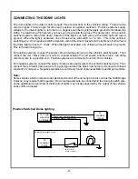
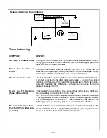
5) Route the wiring harnesses throughout the vehicle as necessary.  (Refer to the Wiring Diagrams on

pages 6 and 7 of this manual as well as the wiring instructions for the individual components and

accessory options being installed).  Be sure that all wiring is protected from sharp edges and is routed
in such a manner that it will not be pinched when all components and interior trim are fully installed.  Be
sure to leave enough slack in the wiring at each component to allow working room.

6) Remove all A/V system components from their packaging and place them loosely in the vehicle at

their respective locations.

7) Connect all components together (electrically) and verify proper operation of all system functions.

Note:  This is best done BEFORE, components have been permanently mounted.

8) After verifying proper operation of the system, proceed to mount of each component.
9) When all components are mounted, recheck function of entire system again to ensure that no wiring

was pinched or connected improperly during final installation.

GENERAL SYSTEM CONFIGURATIONS:

The following is intended to provide some of the system configurations that are possible with the VOD701
and VOD702 series Drop Down Video Systems:

System 1:

   Video Monitor without TV tuner (VOD701), with DVD and FM modulator.

-All wiring necessary is included with this package.

-Headphones are connected into the headphone jacks on the monitor itself (Sold sepa-
rately)

System 2:

   Video Monitor with TV tuner (VOD702), with DVD and FM modulator (Sold separately).

-2-

Notes :

          There are a few audio output options that can be added as follows:
          a) Wired headphone jacks can be added to a VOD701/VOD702 system.  Refer to the wiring
              diagram on page 6/7.
          b) Additional speakers can be added to a VOD701 and VOD702 system using the speaker
             outputs.  Refer to the wiring diagram on page 6/7.
          c) Wireless Headphones (P/N IR2CHS).

         The VOD701 and VOD702 video systems are only intended for an overhead, drop down
         installation.  It is not intended for Seatback or any other  type of mounting.  The hinging mecha-
         nism is designed for horizontal, drop down use only.

Содержание VOD701

Страница 1: ...Installation Guide ELECTRONICS CORP VOD701 Drop Down Video Monitor with DVD VOD702 Drop Down TV Video Monitor with DVD ...

Страница 2: ...r a person to drive a motor vehicle which is equipped with a television viewer or screen that is located in the motor vehicle at any point forward of the back of the driver s seat or that is visible directly or indirectly to the operator of the motor vehicle ...

Страница 3: ...LS REQUIRED 2 Phillips Screwdriver 1 Phillips Screwdriver Utility or Razor Knife or Shears Wire Strippers Upholstery hook tool for removal of panels as necessary Electrical Tape Masking Tape Multimeter to verify 12 volt DC and continuity Do not use a test light or logic probe Marker pen to mark headliner Scribe to mark trim ring if used Misc electrical connectors to connect to vehicle power source...

Страница 4: ... Connect all components together electrically and verify proper operation of all system functions Note This is best done BEFORE components have been permanently mounted 8 After verifying proper operation of the system proceed to mount of each component 9 When all components are mounted recheck function of entire system again to ensure that no wiring was pinched or connected improperly during final...

Страница 5: ...ome light is in stalled The monitor should be located in such a manner that it can be comfortably viewed by rear seat passengers NEVER INSTALL THE MONITOR IN A PLACE WITHIN THE DRIVER S VIEW THIS IS NOT ONLY DANGEROUS BUT IT IS ALSO ILLEGAL IN MANY STATES 4 Once the mounting location of the monitor has been determined there may be additional prepara tion work necessary depending on the vehicle str...

Страница 6: ...nsole in the areas where the cut will be made 3 Mark the cut to follow the necessary contour of the roof The suggested method of marking is as follows A First mark the narrowest point of the mini console on the masking tape Be careful to consider not only vertical location but fore aft location B Using the handle of a screwdriver make a transfer marking tool See diagram below Place the tool agains...

Страница 7: ...oof Roof Support Headliner 5 x9 x3 4 Plywood Block or Optional VOHBKT 4 Self drilling screws not supplied Mini Console Video Unit 4 8 flat washers 4 8x3 4 self tapping screws 5 MOUNTING THE MINI CONSOLE ...

Страница 8: ...the second Mini Din connector on the main PCB as in steps 2 and 3 above A V Source Definitions 1 VCP or VCP with TV Tuner Right Mini Din on main PCB 2 2nd VCP or game or DVD etc left Mini Din 3 AUX IN VCP Game or future DVD etc 4 Built in DVD 6 VOD701 FM Modulator Dash Radio 12 VDC Power and Ground Hard Wired FM Modulator Output Am Fm Antenna Satalite Radio TO FACTORY RADIO Black Ground Optional R...

Страница 9: ...y part number 8010730 This second harness would plug into the second Mini Din connector on the main PCB as in steps 2 and 3 above A V Source Definitions 1 TV Tuner 2 VCP Mini Din on main PCB 3 AUX IN game or future DVD etc 4 Built in DVD FM Modulator Dash Radio 12 VDC Power and Ground Hard Wired FM Modulator Output Am Fm Antenna Satalite Radio TO FACTORY RADIO Black Ground Optional Remote Headphon...

Страница 10: ...pod 4 If the rear seat occupant s want to listen to Sirius on channel B and not on the vehicle radio the Sirius modulator output can be shut off using the Sirius commander Check the Sirius owner s manual for the proper procedure When the Sirius modulator is shut off Sirius audio can still be switched to the POD modulator FTR300 using the POD remote control Using an Audiovox XM satellite receiver 1...

Страница 11: ...itched system with all the doors closed and the lights out both wires at the dome light will rest at 12vdc When the light is activated one of these wires will switch to ground This is the switching wire For positive systems connect the purple brown Lamp auto wire to the vehicle s switched wire Then connect the red black lamp on wire to a fused constant 12 volt source and the black red lamp common ...

Страница 12: ...nd that power to the wired RF modulator is on Refer to instruc tions with modulator kit Otherwise verify all connections per the wiring diagram on pages 6 and 7 Press Auto Program button Then press CH up or CH down Verify an tenna mounting and connections to the tuner Note Due to the nature of TV signals vehicle motion direction the vehicle is facing distance from the transmitter nearby surroundin...

Страница 13: ... Copyright 2003 Audiovox Electronics Corp 150 Marcus Blvd Hauppauge NY 11788 128 6695 WWW audiovox com For Customer Service Visit Our Website At Product Information Photos FAQ s Owner s Manuals ...

Отзывы: