background image

3). THE MAJOR MAIN SPARE PARTS LIST OF THE DECK

72

NO

STOCK NO

PART NAME

Q’TY

REMARK

1

97SA254830

S1-MECHA

1

1-1

97SA254630

S1-MECHA

1

NTSC VCP

1-2

97PA265131

S1-MECHA

1

NTSC 2•HD Hi-Fi VCP

2

97S8101000

F0QTB12

1

PAL VCR

3

97SA256200

S1-MECHA

1

NTSC VCP

4

97S5500500

CR

1

PAL VCR

5

97SA256900

S1-MECHA

1

6

97SA256700

S1-MECHA

1

7

97SA256800

S1-MECHA

1

8

97SA257200

S1-MECHA

1

9

97SA313200

S1-MECHA

1

10

97SA260100

S1-MECHA

1

11

97SA255800

S1-MECHA

1

12

97SA256600

S1-MECHA

1

13

97SA257500

S1-MECHA

1

13-1

97SA260200

S1-MECHA

1

14

97S8009500

HVFHF0004AK

1

15

97SA256400

S1-MECHA

1

Содержание AVP-7180

Страница 1: ...READ THE SAFETY PRECAUTIONS IN THIS MANUAL POWER STOP EJECT PLAY FFWD REW CST IN DEW L Hi Fi R REMOTE SENSOR HI FI STEREO DIGITALAUTOTRACKING FULLAUTOMATICSYSTEM AVP 7180 VIDEO CASSETTE PLAYER AVP 71...

Страница 2: ...articular country and locality 4 Leakage current test Confirm specified or lower leakage current between B earth ground power cord plug prongs and externally exposed accessible parts RF terminals ante...

Страница 3: ...TOTAL CONTENTS 1 SECTION 1 GENERAL 2 SECTION 2 CABINET MAIN FRAME 6 SECTION 3 ELECTRICAL 13 SECTION 4 MECHANISM 34...

Страница 4: ...SECTION 1 GENERAL 2 CONTENTS 1 1 SPECIFICATIONS 3 1 2 IDENTIFICATION AND OPERATION OF CONTROLS 4...

Страница 5: ...o Signal System NTSC type color signal Tape Width 12 65mm 1 2 inch Tape Speed SP 33 35 mm s LP 16 67 mm s SLP 11 12 mm s Maximum PlayBack Time 480min with T 160 Video cassette tape SLP MODE FF REW Tim...

Страница 6: ...he PLAYBACK mode the VCP enters the forward picture search mode If pressed in STOP mode then the tape will fast forward at high speed The FF indicator lamp will light up in orange Cassette In lamp Hi...

Страница 7: ...in your area ANT IN Connect the TV antenna to this terminal VIDEO OUT Connect this terminal to VIDEO IN terminal of your television using the RCA cord provided AUDIO OUT L R Connect this terminal to A...

Страница 8: ...ET MAIN FRAME 6 CONTENTS 2 1 CABINET DISASSEMBLY 7 1 COVER TOP 2 COVER BOTTOM 3 PANEL FRONT AS 2 2 CIRCUIT BOARD DISASSEMBLY 9 1 PCB MAIN AS 2 3 EXPLODED VIEW 10 1 MAIN CHASSIS 2 PANEL FRONT 2 4 PACKI...

Страница 9: ...NET DISASSEMBLY 7 1 COVER TOP Remove four screws see Fig 2 1 Lift the COVER TOP with holding the back of it and remove it 2 COVER BOTTOM Remove one screw to remove the COVER BOTTOM see Fig 2 2 Fig 2 1...

Страница 10: ...ONT AS Remove the COVER TOP See Fig 2 1 Remove the COVER BOTTOM See Fig 2 2 Press five stoppers in direction of the arrows to disengage the top side of the panel front toward to remove it See Fig 2 3...

Страница 11: ...1 PCB MAIN AS Remove six screws and disassemble the DECK mechanism see Fig 2 5A Press two stoppers in direction of the arrow see Fig 2 5B and separate the Main Chasis from the Main PCB by lifting the...

Страница 12: ...TAPPTITE 1 TT2 BIN 4X12 MFZN COVER BOTTOM FIX 6 97PE101600 PCB MAIN AS 1 DV S104NY RJ 6 1 97PB239600 CASE SHI PREAMP AS 1 DV S104NY RJ 7 97P0471200 COVER TOP 1 SECC TO 5 8 7173401212 SCREW TAPPTITE 4...

Страница 13: ...on Remark 1 97P0318900 PANEL FRONT 1 HI PS VO 2 97P1358300 KNOB FUNCTION 1 ABS NATURAL 3 97P4217300 CUSHION DOOR 1 FELT T1 0 4 97P3038000 SPRING F L DOOR 1 SWPB 1082J 5 97P1820800 DOOR F L 1 ABS 6 97P...

Страница 14: ...925400 PAD FRONT BACK 1 EPS 2 97P4801300 POLYBAG FOR SET 1 P E FOAM 3 97P5045900 BOX CARTON 1 EX225 K200 EX225 4 97P9560000 MANUAL OWNERS 1 ALL MODEL DV S102N SJ 5 97P88OP315 CABLE RCA 1 2P 2P 1 5M 6...

Страница 15: ...TMENT 14 1 SERVO LOGIC CIRCUIT ADJUSTMENT METHOD 3 2 CIRCUIT DIAGRAMS 15 1 CONNECTION DIAGRAM 2 POWER CIRCUIT DIAGRAM 3 SERVO SYSCON CIRCUIT DIAGRAM 4 VIDEO NOR AUDIO CIRCUIT DIAGRAM 5 HI FI PRE AMP C...

Страница 16: ...3 2 CIRCUIT DIAGRAMS 15 1 CONNECTION DIAGRAM...

Страница 17: ...16 2 POWER CIRCUIT DIAGRAM...

Страница 18: ...IME DIV 5ms DIV 1 3 P502 6 PLAY MODE DC VOLT DIV 1V DIV TIME DIV 2ms DIV 1 2 IC601 29 PLAY MODE DC VOLT DIV 1V DIV TIME DIV 5ms DIV 1 4 P502 3 PLAY MODE DC VOLT DIV 1V DIV TIME DIV 53ms DIV 1 5 IC501...

Страница 19: ...18 3 SERVO SYSCON CIRCUIT DIAGRAM...

Страница 20: ...C VOLT DIV 100mV DIV TIME DIV 10ms DIV 2 2 IC302 1 PLAY MODE AC VOLT DIV 100mV DIV TIME DIV 10ms DIV 2 4 IC301 39 PLAY MODE AC VOLT DIV 500mV DIV TIME DIV 10ms DIV 2 6 IC301 59 PLAY MODE AC VOLT DIV 2...

Страница 21: ...20 4 VIDEO NOR AUDIO CIRCUIT DIAGRAM...

Страница 22: ...21 2 1 IC401 13 PLAY MODE AC VOLT DIV 100mV DIV TIME DIV 2ms DIV 2 1 IC401 1 PLAY MODE AC VOLT DIV 500mV DIV TIME DIV 2ms DIV...

Страница 23: ...22 5 Hi Fi PRE AMP CIRCUIT DIAGRAM...

Страница 24: ...23 6 A V IN OUT CIRCUIT DIAGRAM...

Страница 25: ...4 CTL REF 5 C PWM 6 I LIMIT 7 Vcc 13V 8 GND 9 IC GND 10 N C PJ201 1 CTL 2 CTL 3 GND 4 PB AUDIO HEAD P503 1 LM 2 LM P401 1 SP L 2 SP commom 3 SP R 4 GND 5 A FM R 6 A FM common 7 A FM L P502 1 VCC 12V...

Страница 26: ...7 1C LOCATION POSITION IC301 5E IC302 5F IC401 2F IC501 2C IC502 5D IC503 2B IC504 3D H701 5A X301 5E X601 3B IC801 5F IC802 4F IC251 1D 2 COMPONENTS LOCATION GUIDE I C X TAL TR SEMI VOLUME CONNECTOR...

Страница 27: ...m C 7 5 mm D 10 0 mm E 12 5 mm F 15 0 mm G 17 5 mm H 20 0 mm G 17 5 mm H 20 0 mm J 22 5 mm K 25 0 mm X Auto Insertion Z Auto Insertion Tolerance Symbol Tolerance F 1 G 2 J 5 K 10 M 20 N 30 Value Examp...

Страница 28: ...er Q Mica Oil T Tantal Distance Code Voltage 0J 6 3V 1A 10V 1C 16V 1D 20V 1E 25V 1V 35V 1G 40V 1H 50V 1J 63J 2A 100V 2B 125V 2C 160V 2D 200V 2E 250V Characteristic Capacitance Temperature Coefficient...

Страница 29: ...AMP LA70020 3 IC502 1BA6209 IC BA6209 3 IC504 1MC4558C IC OP AMP MC4558C KA4558 3 IC801 1K1A7806P1 IC REGULATOR KIA7806PI 3 IC802 1PQ12RF11 IC REGULATOR PQ12RF11 3 JK601 97P6314800 JACK PIN DPAM 9801...

Страница 30: ...MF 4X7 TP 5 C321 CEXF1E220A C ELECTRO 25V RSM 22MF 6 3X7 5 C322 CEXF1H109A C ELECTRO 50V RSM 1MF 4X7 TP 5 C323 CEXF1H109A C ELECTRO 50V RSM 1MF 4X7 TP 4 C331 HCLK101JCA C CHIP CERA 50V SL 100PF J 2012...

Страница 31: ...04NY RJ 6 C251 CCZF1H103Z79TD1664 C CERA 50V F 0 01MF Z 6 C254 CCZF1H103Z79TD1664 C CERA 50V F 0 01MF Z 6 C256 CCZF1H103Z79TD1664 C CERA 50V F 0 01MF Z 6 C271 CCZF1H103Z79TD1664 C CERA 50V F 0 01MF Z...

Страница 32: ...TING 6 JP116 85801065GY WIRE COPPER AWG22 1 0 65 TIN COATING 31 6 JP008 85801065GY WIRE COPPER AWG22 1 0 65 TIN COATING 6 JP009 85801065GY WIRE COPPER AWG22 1 0 65 TIN COATING 6 JP010 85801065GY WIRE...

Страница 33: ...R712 RD AZ161J R CARBON FILM 1 6 160 OHM J LVL LOC PART CODE PART NAME PART DESC 6 JP117 85801065GY WIRE COPPER AWG22 1 0 65 TIN COATING 6 JP118 85801065GY WIRE COPPER AWG22 1 0 65 TIN COATING 6 JP119...

Страница 34: ...2K OHM J 6 R806 RD AZ472J 79TD0117 R CARBON FILM 1 6 4 7K OHM J LVL LOC PART CODE PART NAME PART DESC 6 R713 RD AZ221J 79TD0111 R CARBON FILM 1 6 220 OHM J 6 R714 RD AZ511J 79TD0151 R CARBON FILM 1 6...

Страница 35: ...ement of the S T Slant Pole Assembly 54 6 Replacement of the Drum Price Assembly 55 7 Replacement of the Capstan Motor 56 8 Replacement of the ACE Head Total Assembly 56 9 Replacement of the L C Brack...

Страница 36: ...AM switch which the L C motor operates The cassette in driving of the S1 Mecha Deck undergoes a process as follows When a cassette is inserted F L Drive Rack falls out MICOM recognizes a point of time...

Страница 37: ...nsmitted at the Start Sensor If there is no safety tab in a cassette the Deck mode transfers to the Playback mode The cassette out operation The Cassette Holder Assembly is located at the entrance of...

Страница 38: ...rks when the END START sensor is on during the FF REW operation and it conducts the review and cue operation temporarily The FF REW mode conducts Direct operation and when the deck stops it transfers...

Страница 39: ...you want to stop the operation of tape during the playback of a cassette tape or recording which is the waiting point of the Key in for the next operation When you insert a cassette tape with a safet...

Страница 40: ...backward with a fixed speed At this time a cassette transits backward similarly B The configuration of appliances a The tension pole is in the given location b The band brake is separated from the S R...

Страница 41: ...he T Reel Table at a constant speed When the Slow function is added it can run at the PLAY mode B The configuration of appliances a The Tension Pole is in the given location b The Band Brake is attach...

Страница 42: ...41 3 TIMING CHART OF S1 MECHA MECHANISM...

Страница 43: ...42 4 S1 MECHA DECK WIRE DIAGRAM WIRE DIAGRAM APPLIED TO ONLY RECORD MODEL ITEM ITEM IS DELETED AT VCP MODEL...

Страница 44: ...EAD 3 AUDIO HEAD 4 AUDIO HEAD 5 GND 6 AUDIO ERASE D DRUM MOTOR 1 VCC 12V 2 CONTROL 3 PG OUT 4 NONCONNECT 5 GND 6 FG OUT E CAPSTAN MOTOR F CAM SWITCH 1 VCC 5V 2 F R 3 FG OUT 4 CTL Ref 5 CTL 6 I LIMIT 7...

Страница 45: ...4 2 MAINTENANCEANDCHECKINGOFMAJORSYSTEM 44 1 NAMES OF MAJOR PARTS AND AREA ASSEMBLING DIAGRAM OF DECK A Deck top view...

Страница 46: ...45 B Deck bottom view...

Страница 47: ...g table CLEANING AND GREASING A Cleaning a Tape Running Mechanism Clean it every 500 hours of actual using time Tension Pole S Slant Pole Ace Head S Guide Post Video Head Drum Ass y T Guide Post FE He...

Страница 48: ...rom time to time even if the deck is not used Replace all belts every 2 years However the condition of belts is good enough for use you can keep using it Maintenance period Hrs Name 1000 2000 3000 400...

Страница 49: ...E METER KM 300NV K MEDIA Measurement of Reel Torque KM 300RV K MEDIA KM 300NFF K MEDIA 4 DIAL TORQUE GAUGE Measurement of S T Sub Brake 5 TENTELO METER T2 H7 UM Measurement of Back Tension 6 PIN SPIND...

Страница 50: ...SKETCH OF JIGS AND TOOLS 49...

Страница 51: ...ew 2 of the Top Plate fixing screws tightened with the Main Chassis d Unscrew 4 of the Deck Assembly fixing screws tightened with the Main Chassis e Disassemble the Deck Ass y from the Main Chassis by...

Страница 52: ...Lift the right side of the Cassette Holder Ass y up and disassemble it after pushing it thoroughly to the cassette out direction Anti Arrow Direction but be cautious of its distortion d Turn the Shaft...

Страница 53: ...ub Brake Spring connected to the Main Base Press from the hook d Turn the S Sub Brake Ass y to the counter clockwise direction and lift it up for disassembly e Release the Tension Lever Spring from th...

Страница 54: ...and lift it up to separate from the Main Base Press Be cautious of breakage of Hook b Disassemble the Pinch Lever Spring c Disassemble the Pinch Lever Total Ass y next the Poly Washer but be careful n...

Страница 55: ...ED Prism tightened with the Main Base Press and remove the LED Prism and the Clutch Lever d Unscrew 2 of the fixing screws 1 for the Loading Gear Bracket Ass y tightened with the Cassette Guide BRKT a...

Страница 56: ...e adjustment of Running Mechanism is needed adjust depending on the adjustment method of the Running Mechanism Refer to the Chapter 5 PICTURE 3 6 NOTE In disassembling the Drum Price Ass y pay attenti...

Страница 57: ...part of the Deck Ass y 8 REPLACEMENT OF THE ACE HEAD TOTAL ASSEMBLY PICTURE 3 7 a Unscrew 2 of the fixing screws for the ACE Head Total Ass y and disassemble the ACE Head Total Ass y but be careful no...

Страница 58: ...e disassembling it a Disassemble the L C Bracket Total Ass y b Disassemble the Reel Belt before removing the Poly Washer c Disassemble the Reel Gear Total Ass y d Unscrew the fixing screws for the LED...

Страница 59: ...Before and after assembling the L C Bracket Total Ass y check the assembling location for the Cam Switch the F L Sub Rack and the Cam Gear Refer to the Picture 4 1 c Check the assembling location of t...

Страница 60: ...oading Ass y should be disassembled and assembled at the EJECT mode 3 MEASUREMENT OF THE PRESSURE OF THE PINCH ROLLER a Gently insert a cassette tape into the deck for Loading and push the PLAY button...

Страница 61: ...e operation becomes stable About 10 to 20 seconds b Set the Tentelometer as shown in the picture 4 4 and measure the value of tension Specification 2 28g c When the value is out of the specification m...

Страница 62: ...adjust the Tape Transporting System in these following cases There is some noise on the screen during the playback The tape has been damaged The components of the Tape Transporting System have been re...

Страница 63: ...k PG Prior Setting of the path wave Adjustment for the entrance side Envelope wave Adjustment for the exit side Envelope Fine Adjustment for the entrance exit side Envelope Adjustment of Audio Adjustm...

Страница 64: ...and the entrance exit side Lead Line of Drum while the tape is running b If there is any crack or fold on the tape adjust for smooth run of the tape by rotating the S T Guide Roller 1 2 Tilt Adjustme...

Страница 65: ...0 25mm turn the screw to the counter clockwise direction as step C If the gap is less than 0 25mm turn the screw to the clockwise direction as step TAPE GUIDE POST TAPE Adjust the TILT Adjustment Scre...

Страница 66: ...OF STRAIGHTNESS Connect the Channel 1 CH1 of the Oscilloscope to the TP01 2 CTL Pulse and CH2 to the TP01 4 Envelope Wave and EXT Trigger to the TP01 3 Switching Pulse And then playback the test tape...

Страница 67: ...heck if the Envelope Wave of the Oscilloscope changes constantly while turning the Tracking VR to the CW CCW direction b If the Envelop Wave of the Oscilloscope at the entrance or and the exit side ch...

Страница 68: ...he A C Head Screw of Picture 5 2 Specifications Minimum Output 8 5 12 5dBm The output difference between 1MHz and 6MHz 2 4dBm The Level variation of 6MHz Audio within 1dBm c Check if there is any seve...

Страница 69: ...osition g If every step is acceptable apply the lock paint to the A C Head Screw and CHECKING OF THE STRAIGHTNESS OF THE EXCHANGEABLE TRACKING FINAL INSPECTION Make sure no tape wrinkle is caused at e...

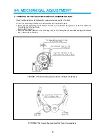
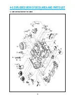
Страница 70: ...4 6 EXPLODED VIEW OF DECK AREA AND PARTS LIST 69 1 EXPLODING VIEW OF THE DECK...

Страница 71: ...70...

Страница 72: ...00 CST HOLDER AS 1 13 97SA257100 S SUB BRAKE AS 1 14 97S1800600 F L DOOR OPENER 1 15 97SA256700 S REEL TABLE AS 1 16 97SA256800 T REEL TABLE AS 1 17 97SA257000 TENSION LEVER T T AS 1 18 97S8009500 FF...

Страница 73: ...97S8101000 F0QTB12 1 PAL VCR 3 97SA256200 S1 MECHA 1 NTSC VCP 4 97S5500500 CR 1 PAL VCR 5 97SA256900 S1 MECHA 1 6 97SA256700 S1 MECHA 1 7 97SA256800 S1 MECHA 1 8 97SA257200 S1 MECHA 1 9 97SA313200 S1...

Страница 74: ...AUDIOVOX SPECIALTY MARKETS CO LP 23319 COOPER DR ELKHART IN 46514 219 266 1886...

Отзывы: