


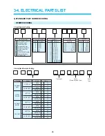
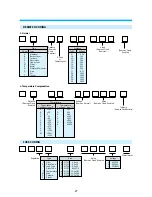

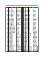


2) ELECTRICAL PART LIST BY ASSEMBLIES
28
1+++ 01
97PC0206P- PACKING
AS
DV-S104NY-RJ
2++
C001
97P4925400
PAD F/B
EPS
2++
C002
97P5045900 BOX
CARTON
EX225*K200*EX225
2++
C003
97P4808500
POLY BAG FOR SET
800*800*T0.5
2++
C004
97P4502200
LABEL SERIAL A
ART PAPER STICKER
2++
C005
6520010020 STAPPLE
M20
1+++ 02
97PC0206A-
ACCESSORY AS
DV-S104NY-RJ
2++
D001
97P9560000
MANUAL OWNERS
ALL MODEL
2++
D002
97P880P815
CABLE RCA
3P-3P 1.5M
2++
D003
97P0424100
COVER ACCESSORY
LD-PE T0.1
2++
D004
97P7702800
PLUG DC CAR
DLP-1033A5
1+++ 03
97PC0206C-
CHASSIS MAIN AS
DV-S104NY-RJ
2++
A001
97P0610410 CHASSIS
MAIN
HI-PS(V0)
2++
A002
97P0800600
LEG
SBR 80 BLK
2++
A003
97P9340000
LABEL SPEC
PE FILM (ALL MODEL)
2++
A004
7173401211
SCREW TAPPTITE
TT2 BIN 4X12 MFZN
2++
A005
7173401212
SCREW TAPPTITE
TT2 BIN 4X12 BK
2++
A006
7173401211
SCREW TAPPTITE
TT2 BIN 4X12 MFZN
2++
A007
7003300611
SCREW MACHINE
BIN 3X6 MFZN FOR CD PCB
2++
A008
VT0C3-2322
LABEL CD
W/ADH PAPER T0.15X8X32
2++
A009
2233030000
LOCK PAINT
NO-2
2++
A010
97P9339000
LABEL CAUTION A
PE FILM T0.05
2++
A011
7173401211
SCREW TAPPTITE
TT2 BIN 4X12 MFZN
2++
A012
97P0471200
COVER TOP
SECC T0.5
2++
A013
97P0471310
COVER BOTTOM
SECC T0.4
2++
A014
97P9324002
LABEL FUSE
ART PAPER(STICKER)
2++
M001
97PP318910
PANEL FRONT AS
DV-S102NY-SJ
3+
B001
97P0318910
PANEL FRONT
HI-PS(V0)
3+
B003
97P1820800
DOOR F/L
ABS
3+
B004
97P3038000
SPRING F/L DOOR
SWPB 1082J
3+
B006
97P1358300
KNOB FUNCTION
ABS
3+
B007
97P1713400
INDICATOR DEW
GPPS
3+
B008
97P1622000
WINDOW REMO
PMMA
3+
B009
97P4217300
CUSHION DOOR
FELT T1.0
2++
M1000
97PC0211D-
DECK TOTAL AS
S1-MECHA
3+
AD001
97PA265131
DRUM PRICE AS
CYN-K312-SJ
2++
13
97PE101600
PCB MAIN AS
DV-S104NY-RJ
3+
C805
CEXF1V102V 79TD0635 C ELECTRO
35V RSS 1000MF (13X25) TP
3+
DL701
DSR5411H--
LED SR-5411H
(RED)
3+
DL702
DSRM5270A- LED
SRM5270-A,DIPPUSION
3+
DL703
DSRM5270A- LED
SRM5270-A,DIPPUSION
3+
DL704
DSRM5270A- LED
SRM5270-A,DIPPUSION
3+
DL705
DSRM5270A- LED
SRM5270-A,DIPPUSION
3+
DL706
DSRM5270A- LED
SRM5270-A,DIPPUSION
3+
DL709
DSRM5270A- LED
SRM5270-A,DIPPUSION
3+
D501
DS1R481T-- LED
IR
SIR-48IT(P-RANK)
3+
D501A
97S2302200
HOLDER LED
ABS
3+
FH801
97P2332000
HOLDER FUSE AS
FH-51A
3+
F801
5F1GB2021M
FUSE GLASS TUBE
UL/CSA NM 2A 125V MF51
3+
H701
1TS0P1238X
IC UNIT R/RECEIVER
TSOP1238XG1 (38KHZ)
3+
IC302
1LC89962--
IC VIDEO
LC89962
3+
IC401
1LA70020--
IC PRE-AMP
LA70020
3+
IC502
1BA6209---
IC
BA6209
3+
IC504
1MC4558C--
IC OP AMP
MC4558C(KA4558)
3+
IC801
1K1A7806P1
IC REGULATOR
KIA7806PI
3+
IC802
1PQ12RF11-
IC REGULATOR
PQ12RF11
3+
JK601
97P6314800
JACK PIN
DPAM-9801
3+
JK801
97P6310800
JACK DC
YSC-1535
3+
JK802
97P62A0144 C0NN
WAFER
770968-1,4PIN,DUAL
3+
M401
97PB239600
CASE PREAMP AS
DV-S104N
4+
M401A 97P0473900
CASE SHI PREAMP
ET T0.3
4+
M401B 97P0983200
PLATE EARTH-D
SUS 304 CSP T0.15
3+
M402
97P0473700
COVER SHI P/A
ET T0.3
3+
M403
97P0720810
BOARD ANT
HI-PS (V0)
3+
M601A 7175300812
SCREW TAPPTITE
TT2 FLT 3X8 MFZN BK
3+
M701
97P2345000
HOLDER LED F
ABS
3+
M801A 97P4408100
RADIATOR TR
AL UL/CSA
3+
M801B 7173300811
SCREW TAPPTITE
TT2 BIN 3X8 MFZN
3+
PJ201
97P885X091 CONN
AS
6H-4S,120MM
3+
PJ801
97P885X003
CONN AS
2S-2T 140
3+
PT01
97P6269100
CONN WAFER
00-8283-0712-00000
3+
P401
97P62Y0847
CONN FPC
FCZ 125L(BLUE15MM)-07P
3+
P501
97P62T112A
CONN B/B (PLUG)
TKC-GP PLUG 10P
3+
P502
97P62T1126
CONN B/B (PLUG)
TKC-GP PLUG 6P
3+
P503
97P62T13B2
CONN BIB
TMC-A,S0CKET,2.0MM,2P
3+
P504
97P62T12A5
CONN BIB
TAS-X,RECEP2.5MM,5P
3+
P505
97P6268600
CONN WAFER
00-8283-0212-00000
3+
RF601
97P7213000 MODULATOR
RF
HSM-3450MV1
3+
S501
97P0S01300 SENSOR
REEL
RPI-244
3+
S501A
97S2302100
HOLDER REEL SENSOR POM
3+
S502
97P0S01300
SENSOR REEL
RPI-244
3+
S502A
97S2302100
HOLDER REEL SENSOR POM
3+
S503
TRPT38PB3F
TR PHOTO
RPT-38PB3F
3+
S503A
97P2342100
HOLDER P/T
ABS(HF-06601)
3+
S504 TRPT38PB3F
TR
PHOTO
RPT-38PB3F
3+
S504A
97P2342100
HOLDER P/T
ABS(HF-06601)
3+
S505
97P0S02000
SENSOR DEW
HDP-05-A8
3+
X301
5XE3R579AB
CRYSTAL QUARTZ
HC-49/U 3.579545MHZ 15PPM
3+
X501
5XJ8R000UE
CRYSTAL QUARTZ
HC-49/S 8.000000MHZ 30PPM
3+
23
97PB239200
PCB MAIN CHIP AS
DV-S104NY-RJ
4+
C201
HCLK821JCA
C CHIP CERA
50V SL 820PF J 2012
4+
C204
HCFK104ZCA
C CHIP CERA
50V Y5V 0.1MF Z 2012
4+
C213
HCFK104ZCA
C CHIP CERA
50V Y5V 0.1MF Z 2012
4+
C261
HCBK103KCA
C CHIP CERA
50V X7R 0.01MF K 2012
4+
C266
HCLK681JCA
C CHIP CERA
50V SL 680PF J 2012
4+
C303
HCBK473KCA
C CHIP CERA
50V X7R 0.047MF K 2012
4+
C304
HCBK103KCA
C CHIP CERA
50V X7R 0.01MF K 2012
4+
C306
HCLK300JCA
C CHIP CERA
50V SL 30PF J 2012
4+
C308
HCLK270JCA
C CHIP CERA
50V SL 27PF J 201
4+
C311
HCLK201JCA
C CHIP CERA
50V SL 200PF J 2012
4+
C312
HCLK101JCA
C CHIP CERA
50V SL 100PF J 2012
4+
C324
HCLK390JCA
C CHIP CERA
50V SL 39PF J 2012
4+
C325
HCFK104ZCA
C CHIP CERA
50V Y5V 0.1MF Z 2012
4+
C327
HCLK100CCA
C CHIP CERA
50V SL 10PF C 2012
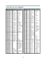
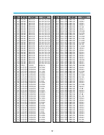
LVL LOC
PART-CODE
PART-NAME
PART-DESC
LVL LOC
PART-CODE
PART-NAME
PART-DESC
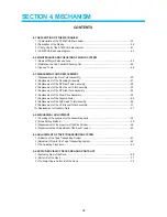
Содержание AVP-7180
Страница 4: ...SECTION 1 GENERAL 2 CONTENTS 1 1 SPECIFICATIONS 3 1 2 IDENTIFICATION AND OPERATION OF CONTROLS 4...
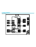
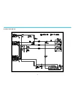
Страница 16: ...3 2 CIRCUIT DIAGRAMS 15 1 CONNECTION DIAGRAM...
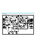
Страница 17: ...16 2 POWER CIRCUIT DIAGRAM...
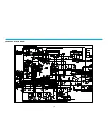
Страница 19: ...18 3 SERVO SYSCON CIRCUIT DIAGRAM...
Страница 21: ...20 4 VIDEO NOR AUDIO CIRCUIT DIAGRAM...
Страница 23: ...22 5 Hi Fi PRE AMP CIRCUIT DIAGRAM...
Страница 24: ...23 6 A V IN OUT CIRCUIT DIAGRAM...
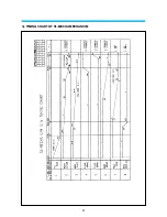
Страница 42: ...41 3 TIMING CHART OF S1 MECHA MECHANISM...
Страница 43: ...42 4 S1 MECHA DECK WIRE DIAGRAM WIRE DIAGRAM APPLIED TO ONLY RECORD MODEL ITEM ITEM IS DELETED AT VCP MODEL...
Страница 46: ...45 B Deck bottom view...
Страница 50: ...SKETCH OF JIGS AND TOOLS 49...
Страница 70: ...4 6 EXPLODED VIEW OF DECK AREA AND PARTS LIST 69 1 EXPLODING VIEW OF THE DECK...
Страница 71: ...70...
Страница 74: ...AUDIOVOX SPECIALTY MARKETS CO LP 23319 COOPER DR ELKHART IN 46514 219 266 1886...


