Audiosmile LBM MK2 Скачать руководство пользователя страница 25

Updated Step)

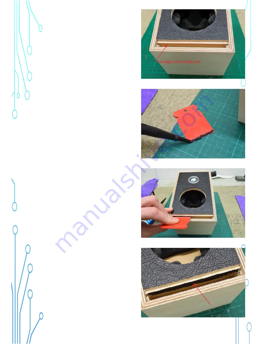
Use silicone sealant to seal the join 
between front baffle and port edge as 
pictured.

A scraper or spatula can help press 
sealant in the join. Perhaps a business card 
from somebody you don’t like can suffice.

Be careful not to make the cabinet messy 
with sealant.

Содержание LBM MK2

Страница 1: ...AUDIOSMILE LBM MK2 DIY ASSEMBLY GUIDE High Resolution Images...

Страница 2: ...x2 Cabinet damping foam 25 x 30cm not pictured Connectors Link socket x2 RCA x3 Volume knob Source knob Source switch Power switch 16 way IDC socket 6 way JST socket 3 5mm jack socket DC power socket...

Страница 3: ...1 5mm and 3mm Spanner set open end 8mm 10mm 12mm 14mm 19mm adjustable Wire cutters side cutters Sharp craft knife Scissors Sand paper 120grit Wood glue Quality PVA e g Titebond or EvoStik Masking Pain...

Страница 4: ...ls carefully and remove any tape that is labelled pull Do not bend the panels they are delicate In addition to the packing tape the cabinet panels are backed with tape to strengthen them and help with...

Страница 5: ...l port pieces so they will fit nicely in to the rebate slots It is recommended to do this over a dust bin or using a vacuum cleaner to collect dust as it falls A knife blade can may help to remove stu...

Страница 6: ...t rebates A1 A2 Port Rebates B1 B2 Port Rebates C1 C2 V grooves 1 and 2 65mm 7 Insert port piece A in port rebate A1 on the right side of the cabinet panel as pictured Align it to the top of the T sha...

Страница 7: ...he T shaped cut 10 Place glue in port rebate B3 and V groove 3 and 4 11 Hold the cabinet closed and align the join 12 Hold the cabinet so it doesn t change shape Press port piece B in to port rebate B...

Страница 8: ...front and back 14 Turn the cabinet so it is facing up as pictured Place the baffle temporarily in the cabinet to ensure the cabinet is square 15 Carefully align the corner joint and hold it closed wit...

Страница 9: ...the joint and tape it Remove the baffle 17 Place a thick line of glue on one long edge of port piece C 18 Slide Port Piece C in to rebates C1 C2 until it is flat with the baffle rebate The thick line...

Страница 10: ...panel supports must be positioned correctly to match Black marks on the support pieces should be on the right side Also the holes are placed away from the cabinet top and bottom edge Please view the i...

Страница 11: ...a vice with a soft towel to hold the panel Alternatively a friend could be very helpful Also it is a good idea to place tape on one side of the spanners so they do not scratch the back panel NOTE Aft...

Страница 12: ...are spaced 14 5mm which is not a standard size so an adjustable spanner will help The nut is 19mm Lug 24 Hold the master panel in the vice Install the 3x RCA connectors Begin with the RCA in the corn...

Страница 13: ...he front Without a special tool it is difficult to make the nut very tight Therefore it is recommended to place a small amount of glue around the body of the connector to keep it secure Install a grou...

Страница 14: ...is 14mm Make it so 28 The power switch has two nuts Put one nut at the bottom of the switch shaft The shaft has a slot in it use a small amount of blu tack or silicon sealant to fill the slot so it do...

Страница 15: ...30 Install the DC Jack The nut is 10mm 31 Install the Link Connector with the lug to the bottom of the panel The flats are 14 5mm The nut is 19mm...

Страница 16: ...wn Insert the Power Connector as shown the gaps face towards you Ribbon Socket Power Socket Switch PCB Power PCB 6 holes Gaps 33 Turn the PCB over and solder the pins 34 Face the Source PCB with the p...

Страница 17: ...e careful so that the pins of all parts go in the PCB correctly without damage Place the PCB over the long LED legs first then over the large circle switch then on the 3 5mm aux jack You may need to u...

Страница 18: ...ed more heating time for the solder to flow well Cut the long legs of the LED 38 Use a small piece of wire to connect the RCA ground ring to the large hole in the PCB next to that RCA pin Solder the c...

Страница 19: ...Place the Power PCB over the wires as pictured PCB printing to the switches The short leg of the DC Jack positive voltage should connect to the bottom of the 3 holes The long leg of the DC Jack negat...

Страница 20: ...Find the diode and fold the legs at the bottom of the body as pictured 43 Install the diode in the Power PCB as pictured Solder the legs 45 Find the Power Cable and connect the Power PCB to the Main P...

Страница 21: ...he Source Knob larger one and make sure the grub screw is not going to block the switch shaft entering The grub screw is 1 5mm Hex Allen Key 48 Make sure the Source Switch is in the middle setting Put...

Страница 22: ...ting Put the knob on the shaft aimed at the minimum dot Tighten the grub screw 50 Use silicone sealant to seal all the joints of the port pieces and the cabinet front and back It is very important tha...

Страница 23: ...Updated Step The cabinet damping foam is supplied as one sheet It should be cut as shown Updated Step The port damping foam is supplied as one sheet It should be cut as shown...

Страница 24: ...piece as pictured Note Glue on port edge NOT on cabinet bottom edge Baffle rebate Port edge 54 Press the baffle firmly in the cabinet aligned to the top Ensure wires for tweeter and woofer go to the b...

Страница 25: ...seal the join between front baffle and port edge as pictured A scraper or spatula can help press sealant in the join Perhaps a business card from somebody you don t like can suffice Be careful not to...

Страница 26: ...lack Correct wiring is important 56 Press the woofer firmly in the baffle There is a cut out to match the woofer connection plate Screw in the woofer with 4x black screws The screws are 3mm Hex 57 Cut...

Страница 27: ...s pictured Close the cabinet back Affix with 4x silver screws Screws are 3mm Hex 59 Cut 2x pieces of port damping foam 3cm x 6cm Place in the left and right side of the port exit 60 Place the line of...

Страница 28: ...62 Now we can assemble the slave speaker Repeat steps 50 57 The difference is the slave baffle does not have a plug on the tweeter and woofer wires Seal the port with silicon the same as the master sp...

Страница 29: ...he Link Connector pins are numbered Tweeter black to Pin 1 Tweeter red to Pin 2 Woofer black to Pin 3 Woofer red to Pin 4 1 2 3 4 64 Close the cabinet back Affix with 4x silver screws Screws are 3mm H...

Страница 30: ...quieter If the opposite occurs this means the slave speaker has been wired incorrectly with the red and black wires reversed at some point Additional information Phase is a term to describe the relati...

Отзывы: