


AUBER INSTRUMENTS
WWW.AUBERINS.COM
2018.08
P3/11
The set-value can either be a temperature value (with letter “
M
” display on the left)
or a percentage number (with letter “
P
” displayed on the left) of the power output.
The user can rotate the knob to select from 0% to 100% power and from 0 to
932 °F/°C. Press the knob to confirm the value and go to the timer setting.
The step-timer can be set in the
HH:MM
format, ranging from 00:00 to 99:00, or a
special code which can be
SKIP
,
HOLD
,
END
, or
CONT
. Please see later sections
for details. If the step-timer a step is set to
END
or
CONT
, the user won’t be
prompted with the next step.
4.7.
Start the Program
Simply press down the RUN key to start the program. The top window will show
“
RUN
” shortly and then show probe reading and start running the first valid step.
RUN
1 5 0
Figure 8. The top window shows “
RUN
” when the program starts.
4.8.
Make Adjustment On-the-Fly
This controller offers a quick way for users to adjust the set-value and the step-
timer of the current step without going back into the programming menu. It also
allows the program to be jumped from the current step to any other valid step in
the program.
a)
Change the set-value
. When the lower display shows the current set-value,
simply turn the knob in either direction to start editing the value. A flashing dot will
appear at the lower right corner to indicate the set value is being editing. Keep
turning the knob till the desired set-value is shown in the lower window. Then press
the knob to confirm the change, otherwise the new value won’t be saved.
7 8.
1 5 0.
7 8.
1 5 5
.
7 8.
1 5 5.
KNOB
Turn
KNOB
Depr ess
7 8.
1 5 0
.
KNOB
Turn
Figure 9. Changing the set-value while the program is running.
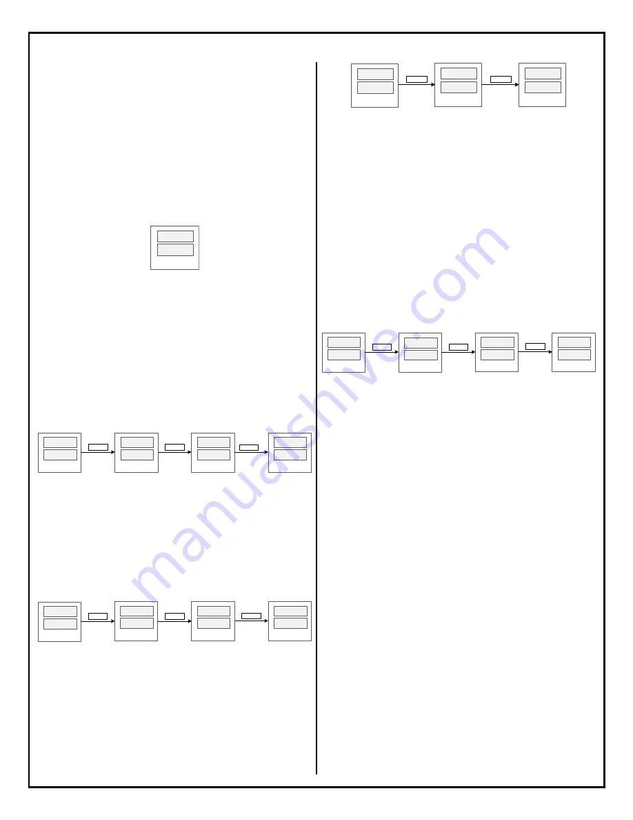
b)
Change the step-timer
. When the lower display shows the current step number,
turn the knob in either direction to start editing the step-timer. A flashing dot will
appear at the lower right corner to indicate the new value hasn’t been saved yet.
Press the knob again to confirm the change, otherwise the new value won’t be
saved. The Figure 10 below shows this operation when the temperature is still
being ramping up to the step’s set-value. So, the top window only shows the
current probe reading. If the step-timer had started, the top window will show the
current time.
7 8.
m - 1.
7 8.
0 0
:
4 5
.
7 8.
m - 1
KNOB
Turn
KNOB
Depr ess
7 8.
0 0
:
5 0
.
KNOB
Turn
Figure 10. Changing the step-timer while the program is running.
c)
Pause the timer
. When the temperature reaches the timer-start-point, the step-
timer will start counting down time. The user can manually pause the timer by
short-pressing the HOLD key. When the timer is paused, the top window will show
“
HOLD
.
”. To resume the current step- timer, press the RUN key shortly and the
controller will show “
RUN
” in its top window. The Figure 11 shows how to pause
the timer.
0 0
:
4 5.
m- 1.
HOLD
.
1 5 0.
HOLD
Press
RUN
m- 1.
RUN
Press
Figure 11. Operations to pause and to resume the step-timer.
When the timer is paused from the key pad, a dot will also appear in the right
corner of “
HOLD
.
” indicates that the timer is temporarily paused and it can be
resumed. This is different from setting/changing the step-timer to
HOLD
, where
the timer display is “
HOLD
” (no dot) and pressing the RUN key will make the
program continue to the next step.
d)
Jump to another step
. While the program is running, it can be jumped from
the current step to another step in the program. This operation is not valid if the
program is ended or stopped. The operation is shown in Figure 12. Press the knob
to bring up the Quick Access Menu. The top window will show “
STEP
” and the
current step number will be shown in the lower window. Turn the knob to find the
desired step number and press down the knob to confirm. If you select a valid step
number, the controller will jump to the selected step and executing the new step.
If you select the current step number or a non-valid step number, the controller will
take no action and simply return to the main operation interface. Here, a non-valid
step refers to a step whose step-timer is set to SKIP or a step behind the last step
of a program.
Step
1.
STEP
3
KNOB
Tur n
RUN
1 6 0.
KNOB
Press
7 8.
1 5 0.
KNOB
Press
Figure 12. Jumping from one step to another while the program is running.
Please note
that all changes that the user makes from the main interface are
temporary. It doesn’t affect the programs that have been saved in the
mPRG
or
bPRG
. The controller will always retrieve the set-value and the step-timer value of
the next step from the saved program.
4.9.
End or Stop the Program
In DSPR320,
End
and
Stop
are different status. When a program has come to its
end, whether the controller will enter the
End
or the
Stop
status depends on the
parameter
EO
(Ending Option for Mash Mode) and
bEO
(Ending Option for Boil
Mode). Please refer to section 5.7 for details.
Ways to
End
a program:
a)
Wait till the controller finish executing all the programmed steps.
b)
Change the step-timer to “END”. The program will come to its end when the
temperature reaches the timer-start-temperature.
Ways to
Stop
a program:
a)
Press and hold the “STOP” key for about 3 seconds to end the program and
stop all outputs.
b)
Reset the program by going to the Quick Access Menu and select “RST/Y”.
c)
Switch the Operation Mode from one to another will also end the current
program.
d)
Power off the controller and power it on again.
5.
Understand the Controller DSPR320
5.1.
Program Mode
In DSPR320, a Program Mode, or a Mode, can save a program with up to 9 steps.
There are two Modes on DSPR320:
MASH
and
BOIL
. The Program Mode is
indicated by the MASH LED indicator. The intended use of
MASH
Mode is to
control water or wort temperature during a mashing process. The default set-
values of all steps in MASH Mode are 0 degree. The temperature unit depends on


