background image

3-7

3.2.7. RETICLE COLOR/BRIGHTNESS 

ADjUSTMENT 

Your scope has a reticle with two color and 5 degrees of bright-

ness of illumination for each color. The knob of brightness adjust-

ment reticle and color select is located on the side of the body of 

the scope. on the knob there are color dots marking with color of 

illumination of reticle. 

FIGURE 3-6. RETICLE ADjUSTMENT

3.2.8. wINDAGE AND ELEVATION 

The vertical and horizontal adjustments for the scope can be 

achieved by turning the elevation and windage adjustment mech-

anisms (remove dust caps first). Each click is 3/4 MOA (ThOR-2) 

or 1/2 MOA (ThOR-3) . When reaching the maximum range of 

rotation do not use force.

FIGURE 3-7. wINDAGE AND ELEVATION OF THOR

RETICLE ADJUSTMENT KNOB

elevaTIon

WINDAGE

Содержание ThOR Series

Страница 1: ... or attempt to export or otherwise transfer or sell any hardware or technical data or furnish any service to any foreign person whether abroad or in the United States for which a license or written approval of the U S Government is required without first obtaining the required license or written approval from the appropriate Department of the U S Government having jurisdiction in such matters Dive...

Страница 2: ... change without notice is not to be construed as a commitment by ATN Corp ATN Corp assumes no responsibility or liability for any errors or inaccura cies that may appear in this book 2010 ATN Corp All right reserved Register your product warranty online at www atncorp com warranty ...

Страница 3: ... be observed Do not dismantle the device Keep the device clean protect it from moisture sharp tem perature drops and shocks Be careful not to touch the glass surfaces If you put finger prints on or contaminate the glass surfaces use only clean and soft materials to clean it Do not leave the device in on position during stops in opera tion Remove the batteries from the device for the period of stor...

Страница 4: ...e off before you remove power remove batteries or disconnect external power supply WARNING ThOR Series operates over a wide operating temperature range 20 C to 60 C Not all lithium batteries are specified over this same temperature span Check the manufacturer s specifications of your selected battery to verify the valid tem perature range WARNING Do not use any battery other than a CR 123A lithium...

Страница 5: ...cts such as coins keys etc Metal objects can cause the batteries to short circuit and become very hot In the case of lithium bat teries a short circuit could cause them to explode WARNING Observe battery manufacturer s guidelines for safe handling and proper disposal of batteries eqUipment limitatiOnS The ThOR Series detector spectral band 7 to 14 mkm pro vides a better penetration through smoke s...

Страница 6: ...ctions 1 11 1 2 6 Optical Functions 1 12 1 2 7 Electrical Functions 1 12 SECTION II ASSEMBLY AND PREPARATION 2 1 2 1 Preparation 2 2 2 1 1 Preparation for Use 2 2 2 1 2 Examination for Operation 2 3 2 2 Assembly 2 4 2 2 1 Remove installation of Quick Release Mount QRM 2 4 2 2 2 Video Output 2 5 2 2 3 External Power Source 2 6 2 2 4 DVC Installation 2 6 SECTION III OPERATION 3 1 3 1 General Informa...

Страница 7: ...Operations 3 8 SECTION IV MAINTENANCE INSTRUCTIONS 4 1 4 1 Preventive Maintenance Checks and Services PMCS 4 2 4 1 1 Purpose of PMCS 4 2 4 1 2 Frequency of Performing PMCS 4 2 4 2 Troubleshooting 4 4 4 2 1 General 4 4 4 2 2 Troubleshooting Procedures 4 4 4 3 Maintenance Procedures 4 5 4 3 1 Scope Maintenance 4 5 4 3 2 Cleaning Procedures 4 5 4 3 3 Preparing for Extended Storage 4 6 ...

Страница 8: ...iii ...

Страница 9: ...1 1 SECTION I introduction ...

Страница 10: ...341 San Mateo Avenue South San Francisco CA 94080 800 910 2862 650 989 5100 650 875 0129 fax info atncorp com www atncorp com 1 1 3 Storage Storage of ThOR should be done in the factory packing and after a thorough PMCS as outlined in Section 4 1 of this manual This will ensure the scope remains in mission ready condition during stor age Batteries should be stored separately from the scope The sco...

Страница 11: ...e environmental conditions specified by the manufac turer This warranty is extended only to the original purchaser Any breach of this warranty shall be waived unless the customer notifies ATN at the address noted below within the applicable warranty period The customer understands and agrees that except for the foregoing warranty no other warranties written or oral statutory expressed or implied i...

Страница 12: ...receipt to our service center ATN Corpora tion at the address noted above All merchandise must be fully insured with the correct postage ATN will not be responsible for improper post age or missing or damaged merchandise during shipment When sending product back please clearly mark the RMA on the outside of the ship ping box Please include a letter that indicates your RMA Name Return Address reaso...

Страница 13: ...ection border patrol officers police SWAT and special operations forces providing them the tools they need to be successful in all field conditions both day and night Uncooled thermal imaging cuts through dust smoke fog haze and other battlefield obscurants Its use cannot be detected as it emits no visible light or RF energy and operates without the use of illuminators or IR lights Figure 1 1 ATN ...

Страница 14: ...atures High resolution digital thermal imaging Compact lightweight and durable housing True magnification High end OLED display Two colors reticle system Rapid start up in 3 seconds Up to 6 hours operation with four lithium batteries One Year Warranty ...

Страница 15: ...dard Components ITEM DESCRIPTION QTY 1 Scope 1 2 Quick Release Mount 1 3 Hard Storage Case 1 4 Lens Tissue 1 5 Lithium Battery CR123A 4 6 RCA Video power Adapter 1 7 Operator s Manual 1 1 Scope The thermal imaging scope 2 Quick Release Mount Used to mount scope to weapon 3 Hard Storage Case A protective case used for shipping storing ThOR and accessories 2 5 3 1 4 6 7 8 ...

Страница 16: ... power sources 7 Operators Manual Provides equipment description use of operator controls and preventative maintenance checks and service 1 2 3 ThOR optional Components The ThOR optional components are shown in Figure 1 4 and presented in Table 1 2 Figure 1 4 Thor Optional Components Table 1 2 ThOR Optional Components DESCRIPTION QTY DVC 1 1 DVC DVC Digital View Clip on dual day low light high res...

Страница 17: ...iew H x V deg 12x9 8x6 Angular resolution mrad 0 6 0 4 Diopter 5 Eye Relief mm 45 Magnification 2x digital 4x 3x digital 6x Digital Zoom 2 Focus Manual Focusing range m 3 to infinity 5 to infinity Diameter of exit pupil mm 10 Distance of the human detection m 915 1350 Distance of the human recognition m 450 675 Reticle Crosshair 2 colors Windage and Elevation Adjustment 2 1 Step of Windage and Ele...

Страница 18: ... 215x77x83 260x77x83 Dimensions inches without bracket 8 5x3 0x3 3 10 2x3 0x3 3 Dimensions L x W x H mm with bracket 215x77x88 260x77x88 Dimensions inches with bracket 8 5x3 0x3 5 10 2x3 0x3 5 Mounting bracket Quick Release Picatinny External power 9 12V DC Other Options Video output Yes Video in Yes Low Battery Indicator Yes ATN reserves the right to change the above specifications at any time wi...

Страница 19: ...tor eyepiece diopter adjustment ring focusing ring battery compartment cover mounting rail The mechanical controls are identified in Figure 1 5 Figure 1 5 ThOR Mechanical Controls DIOPTER ADJUSTMENT RING UNIVERSAL CONNECTOR WITH CAP FOCUSING RING SWITCHBOARD BATTERy COMPARTMENT COVER with screws QUICK RELEASE MOUNT PICATINNY RAILS WINDAGE ADJUSTMENT RETICLE COLOR BRIGHTNESS ADJUSTMENT RUBBER EYE C...

Страница 20: ...om infrared detector is passed to electronics for image processing The signal processing circuitry translates the infrared detector data into an image that can be viewed on the built in OLED display The im age is observed through an eyepiece by operator 1 2 7 electrical function The electronic circuit is powered by replaceable four 3V lithium bat teries CR123A ThOR can be connected to an external ...

Страница 21: ...2 1 SECTION II assembly and preparation ...

Страница 22: ...ING The lithium battery contains sulfur dioxide gas under pressure Do not heat puncture disassemble short circuit attempt to recharge or otherwise tamper with the batteries Turn off equipment if battery compartment becomes unduly hot If possible wait until the batteries have cooled before removing them If you inhale sulfur dioxide seek medical attention The ThOR will operate with four CR123A Lithi...

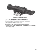
Страница 23: ...ination for operation Before getting started make sure to follow these steps 1 Push ON OFF button on the scope 2 Make sure that the luminance in ocular is present 3 Observe the scene and adjust the diopter and or lens for opti mal image clarity ...

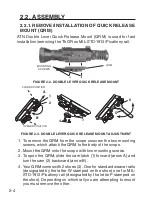
Страница 24: ...nting screws which attach the QRM to the body of the scope 2 Mount the QRM onto the scope with two mounting screws 3 To open the QRM slide the cam latch 1 forward arrow A and turn the cam 2 backward arrow B 4 Your QRM comes with 2 shoes 3 One for standard weaver rails designated by the letter W stamped on the shoe one for MIL STD 1913 Picatinny rail designated by the letter P stamped on the shoe D...

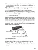
Страница 25: ...onnector used for video trans mission and to connect external power sources RCA video power adapter attaches the scope to the video facilities for video recording or video transmission 1 to the external display though at the same time it accepts the external power supply 2 Connect the scope to an external video display recorder and to an external power supply as follows Figure 2 4 ThOR with Video ...

Страница 26: ...cope output connector socket 3 Attach the RCA video power adapter to the output connector socket 4 Attach the power jack socket of the cable to a 12 V DC 2 A power supply Notes 1 The external power supply plug must have a 6 mm OD con tact with center pin positive 2 Avoid a sudden removal of power source use the power button ON OFF to turn the scope off before you remove bat teries or disconnect ex...

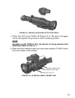
Страница 27: ...l lug into the groove on the mounting surface NOTE Operations with QRM of DVC are similar to the operations with QRM described in Unit 2 2 1 2 Remove the protective cap from connector socket of ThOR Insert DVC connector to the socket Figure 2 8 camera cable connection CONNECTOR SOCKET CABLE CONNECTOR protective cap ...

Страница 28: ...2 8 ...

Страница 29: ...3 1 SECTION III OPERATION ...

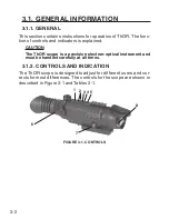
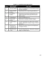
Страница 30: ...ined CAUTION The ThOR scope is a precision electron optical instrument and must be handled carefully at all times 3 1 2 Controls and indication The ThOR scope is designed to adjust for different users and cor rects for most differences The controls for the scope are shown or described in Figure 3 1 and Tables 3 1 Figure 3 1 Controls 1 8 2 3 4 5 6 7 ...

Страница 31: ...ack into hot black cold white mode only in Black and White mode 4 Zoom Button Digital magnification On 5 TOUCH UP Button Maintains an optimum thermal image 6 Diopter Adjust ment Focuses eyepiece lens without the need for glasses Adjusts for sharper image of intensi fier screen 7 Reticle color brightness ad justment knob Adjusts color red or green and brightness 5 steps of reticle 8 Objective Lens ...

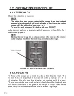
Страница 32: ...r mal scene appears NOTE During the warm up time a logo comes into view on the mono cular display Next the thermal image replaces the logo Figure 3 2 Switchboard of ATN ThOR 3 2 2 FOCUSING To focus the scope you need to adjust the diopter first The scope has an adjustable eyepiece with a range of 5 to 5 diopter Simply turn the diopter clockwise until it stops Then concentrate on any object and slo...

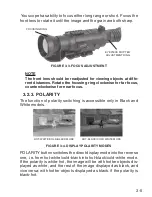
Страница 33: ... function of polarity switching is accessible only in Black and White models Figure 3 4 Display Polarity Modes POLARITY button switches the direct display mode into the reverse one i e from hot white cold black into hot black cold white mode If the polarity is white hot the image will be with hotter objects dis played as white and the rest of the image displayed as black and vice versa with hotter...

Страница 34: ... button is pushed first time the scope will display a scene magnified 2X To reset the magnification to the 1X press ZOOM button again 3 2 6 MANUAL IMAGE REFRESH Degradation of the image image blurring is caused by charge ac cumulation on the detector array Use the TOUCH UP button to maintain an optimum thermal image During this refresh the video will freeze for approximately 0 5 se cond NOTE While...

Страница 35: ...there are color dots marking with color of illumination of reticle Figure 3 6 Reticle Adjustment 3 2 8 WINDAGE AND ELEVATION The vertical and horizontal adjustments for the scope can be achieved by turning the elevation and windage adjustment mech anisms remove dust caps first Each click is 3 4 MOA ThOR 2 or 1 2 MOA ThOR 3 When reaching the maximum range of rotation do not use force Figure 3 7 Win...

Страница 36: ...m the following 1 Use the ON OFF button to turn the scope off 2 Replace the protective cover on the objective lens 3 Disconnect the cable if present Replace the protective cap on the scope output connector socket 4 Return the scope and the cable to the case ...

Страница 37: ...4 1 SECTION IV maintenance instructions ...

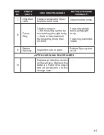
Страница 38: ...e Maintenance Checks and Services SEQ NO ITEM TO CHECK CHECKING PROCEDURE NOT FULLY MISSION CAPABLE IF 1 Complete ness Inventory items by means of comparing with the data specified in this manual Items missing 2 Sight Body Inspect for missing screws or connector cap Screws or connector cap missing 3 Front Lens Cap Inspect for cuts tears and dirt Clean as required Cap torn or cut 4 Battery Compart ...

Страница 39: ... focus ring cannot be moved along the sight body there is free rotation of the focus ring more than 3 4 turn Focus ring able to move along sight body Focus ring cannot be rotate 9 Rubber Eye cup Inspect for cuts or tears Rubber Eye cup torn or cut AFTER CHECKING PROCEDURES 10 Replace protective covers on the lenses Remove the batteries Return the scope and all accessories to the storage case ...

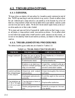
Страница 40: ... actions contact to the service center 4 2 2 Troubleshooting Procedures Troubleshooting procedures are listed in Table 4 2 Table 4 2 Troubleshooting Procedures PROBLEM PROBABLE CAUSE CORRECTIVE ACTION Image is absent Batteries are missing or improperly installed Insert batteries or install cor rectly Batteries are dead Replace batteries Batteries contact sur faces or contact springs dirty or corro...

Страница 41: ... sight body using only a clean soft cloth 2 Moisten the cloth with fresh water and gently wipe the external surfaces except lenses 3 Dry any wet surfaces except lenses with another dry and clean soft cloth 4 Using lens brush carefully remove all loose dirt from the lens es 5 Slightly dampen a cotton swab with ethanol and lightly and slowly wipe the lenses Clean the glass surfaces by circular movem...

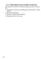
Страница 42: ...torage To prepare the ThOR for extended storage perform the follow ing 1 Check the scope for serviceability as outlined in item 4 1 of this manual 2 Remove the batteries 3 Clean the scope and accessories 4 Replace all items in the case ...

Страница 43: ...4 7 ...
Страница 44: ...ffice 1341 San Mateo Avenue South San Francisco CA 94080 phone 800 910 2862 650 989 5100 fax 650 875 0129 European Office The following countries can use our toll free number 00 800 9102 8620 Austria France Germany Holland Italy Spain Sweden Switzerland For other countries please use 38 048 7770214 or 38 048 7770345 www atncorp com ...

Отзывы: