7
Base MOuNt FOr 12x36
Base Mount for 12x36 was developed for extreme range rifles like the 50 BMG. With 300 MOA of eleva-
tion, ranging in access of 3000 Meters is possible. Used in conjunction with a scope internal adjust-
ments there are three modes of vertical and two modes of horizontal adjustment. It is important to install
the riflescope with the reticle’s convergence point on the center of the scopes optical axis. Along with
the elevation capabilities there is also more than enough windage adjustment in the base to accomplish
this task, regardless of base or installation range requirements. There are several mounting systems
available that facilitate this, but none other than Base Mount for 12x36 that allow this at extreme ranges.
These instructions are intended to help you take full advantage of this remarkable mount.
INstallatION
Base Mount for 12x36 requires Picatinney or slotted weaver style base for attachment to the firearm. It is
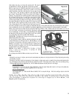
important to keep from over tightening the both the rail
screws and the ring screws
(Fig.15)
. The large bearing
surface on both allows minimal torque on the screws. It
is recommended to grip the short end of an allen wrench
to apply torque so that torque is minimized on the ring
screws, then add another 1/8 turn utilizing the long end
of the wrench. The mounting wing nuts can be tight-
ened adequately using a pair of needle nosed pliers.
Once mounted on the rifle install the scope in the rings
using the above described torque technique applied in
a figure 8 pattern. Be sure that the scope’s crosshair is
square with the receiver and bore. A bore sight helps to
both align the X-hair and in the below described initial
adjustment of the scope.
As stated earlier it is very important to center the scopes optical axis for long range shooting, thus allow-
ing minimal optical distortion. The vertical and horizontal positions of the retical want to be centered in
their respective travel range. Typically this initial zero is then adjusted to the desired point of impact for
the chosen ammunition using the scopes internal adjustments. While this is an acceptable and widely
used practice the end result is to remove the X-hair from the center of the optical axis, even when using
a scope that has a self-centering reticle. The self-centering refers to the position of the reticle in the
scopes field of view not its position relative to the optical axis. Using Base Mount for 12x36 impact can
and should be used to for initial sighting in or zero. Ideally this should be done at 200 yards or 100 yards
if the ballistic curve for your chosen ammo is known.
Referring to Figure use the following sequence:
1. Check the windage for zero. If the crosshair is not centered adjust it by rotat-
ing the a centric inserts via the following method: Use the slot milled into the
top half of each ring to access the holes drilled thru the insert)
(Fig.16)
. Move
the inserts radially to achieve the above described scope picture by inserting a
round rod into the holes drilled in the insert
(Fig.17)
. The shank (blunt end) of a
9/64 drill works perfectly. When the reticle is centered, tighten the ring screws
exerting torque on the short end of the supplied allen wrench. It is not neces-
sary to use the leverage of the long arm to tighten the screws any more than an
additional 1/8 turn.
2. Set Ballistic Cam (BC) “A”
(Fig.18)
on position 2 (200 Yards) by locking the
BC Lock Lever (BCL) “C” in the down position and turning it full CW as viewed
from above.
3. Lock out BC by placing the BC Lock “C” in the up position and run the mount’s
Main Vertical Adjuster (MVA) “B” to its lowest setting by turning it full CW, also.
The mount is now positioned for initial sight in at 200 yards.
4. Using the following graduations sight scope in for 200 yard zero utilizing only the mounts adjusters
“B” and “D”.
Rail screws
Ring screws
Ring screws
Figure 15.
Figure 16.
Direction
Mount/External (Coarse)
Scope/Internal (Fine)
Elevation (Vert.) “B”
3 MOA / Click
1/8 MOA / Click
Windage (Horiz.) “E”
0-20 MOA
1/8 MOA / Click

