background image


Error! Reference source not found.

 [ZigBit 900 MHz Wireless Modules] 

10 


3.2 

Physical/environmental characteristics and outline 

Table 3-5. 

 Physical characteristics. 

Parameters 

Value 

Comments 

Size 

30.0 x 20.0 mm 


Operating temperature range 

-40°C to +85°C 

-40°C to +85°C operational 


3.3 

Pin configuration 

Table 1 ATZB-RF-212B-0-CN Pinout description 

Pin Out  

Pin 

descriptions 

Function 

AVSS 

Analog Ground 

AVSS 

Analog Ground 

DEVDD 

Digital Power input pin 

DEVDD 

Digital Power input pin 

/RST 

REST active low 

/SEL 

SPI select, active low 

MOSI 

SPI data input 

MISO 

SPI data output 

SCLK 

SPI clock 

10 

DIG1 

 Reserved 

11 

FEM_CSD 

 Reserved 

32 

DIG3 

RX TX Indication  

33 

DIG4 

 RX TX Indication (Inverted) 

34 

DIG2 

Tx- Rx time-stamp 

35 

SLP_TR 

Controls sleep, deep sleep, 
transmit start, receive states; 
active high 

36 

SCL 

TWI- EEPROM 

37 

SDA 

TWI- EEPROM 

38 

FEM_CPS 

Reserved 

39 

CLKM 

Master Clock out put  

40 

IRQ 

Interrupt request signal output 

41 

DVSS 

Digital Ground 

42 

DVSS 

Digital Ground 

Содержание ZIGBIT ATZB-RF-212B-0-CN

Страница 1: ... Capability to use MAC address into the onboard EEPROM IEEE 802 15 4 compliant Transceiver 900MHz ISM band Rapid design in with built in Chip Antenna RF Test point using MS 147 RF connector Small physical footprint and low profile for optimum fit in very small application boards Mesh networking capability Easy to use low cost development kit Single source of support for HW and SW Worldwide license...

Страница 2: ... 1 1 Absolute Maximum Ratings 8 3 1 2 Power Supply 8 3 1 3 RF Characteristics 9 3 2 Physical environmental characteristics and outline 10 3 3 Pin configuration 10 3 4 Antenna Orientation Recommendation 11 3 5 Mounting information 11 3 6 Soldering profile 16 3 7 Antenna reference designs 17 4 Section 4 17 4 1 1 General recommendations 17 5 Persistence Memory 18 6 Ordering information 18 7 Agency Ce...

Страница 3: ...that can be used as an RF test port The built in chip antenna is designed and tuned for the ZigBit design to enable quick integration of the ZigBit into any application 1 2 Applications The ZigBit module is compatible with robust IEEE 802 15 4 ZigBee stack that supports a self healing self organizing mesh network while optimizing network traffic and minimizing power consumption For detailed Softwa...

Страница 4: ...TA Over The Air upgrade PA Power Amplifier PCB Printed Circuit Board PER Package Error Ratio RAM Random Access Memory RF Radio Frequency RPC Reduced Power Consumption RTS CTS Request to Send Clear to Send RX Receiver SMA Surface Mount Assembly SoC System on Chip SPI Serial Peripheral Interface SW Software TTM Time To Market TX Transmitter UART Universal Asynchronous Receiver Transmitter USART Univ...

Страница 5: ...r Information technology Part 15 4 Wireless Medium Access Control MAC and Physical Layer PHY Specifications for Low Rate Wireless Personal Area Networks LR WPANs 3 ZigBee Specification ZigBee Document 053474r17 October 19 2007 4 AT86RF212B Datasheet in http www atmel com devices AT86RF212B aspx tab documents ...

Страница 6: ...nsmission and increases its sensitivity This ensures stable connectivity within a larger coverage area and helps develop applications on smaller footprint The MS 147 connector 1 can be used as an RF Test port ZigBit Module contains a complete RF design with all the necessary passive components included The module can be easily mounted on a simple 2 layer PCB with a minimum of required external con...

Страница 7: ...r successful module design in Third party sensors can then be connected directly to the module thus expanding the existing set of peripheral interfaces Every ZigBit Module come pre loaded with Atmel assigned 64 bit MAC address stored in the signature bytes of the device This unique IEEE MAC address can be used as the MAC address of the end product so there is no need to buy a MAC address separatel...

Страница 8: ... this specification is not implied Exposure to absolute maximum rating conditions for extended periods may affect device reliability 2 Attention ZigBit is an ESD sensitive device Precaution should be taken when handling the device in order to prevent permanent damage 3 1 2 Power Supply Table 3 2 Test Conditions unless otherwise stated Vcc 3V Tamb 25 C Parameter Range Unit Supply voltage VDD 1 8 to...

Страница 9: ...ured is Line of Sight at 10ft elevation from Ground at different combinations of orientation of transmitter and receiver with special conditions were there is minimal or no RF interference from other sources For best case orientation of the ZigBits to achieve maximum range refer to section Error Reference source not found Table 3 4 TX power settings PHY_TX_PWR 3 0 Register value Power register set...

Страница 10: ...Analog Ground 2 AVSS Analog Ground 3 DEVDD Digital Power input pin 4 DEVDD Digital Power input pin 5 RST REST active low 6 SEL SPI select active low 7 MOSI SPI data input 8 MISO SPI data output 9 SCLK SPI clock 10 DIG1 Reserved 11 FEM_CSD Reserved 32 DIG3 RX TX Indication 33 DIG4 RX TX Indication Inverted 34 DIG2 Tx Rx time stamp 35 SLP_TR Controls sleep deep sleep transmit start receive states ac...

Страница 11: ...ndicated in this illustration 3 5 Mounting information The Figure below shows the PCB layout recommended for a ZigBit module Neither via holes nor wires are allowed on the PCB upper layer in the area occupied by the module As a critical requirement RF_GND pins should be grounded via several via holes to be located right next to the pins thus minimizing inductance and preventing both mismatch and l...

Страница 12: ...Error Reference source not found ZigBit 900 MHz Wireless Modules 12 Figure 3 1 ATZB RF 212B 0 CN Dimensions ...

Страница 13: ...Error Reference source not found ZigBit 900 MHz Wireless Modules 13 Figure 3 2 ATZB RF 212B 0 CN Pinout ...

Страница 14: ...Error Reference source not found ZigBit 900 MHz Wireless Modules 14 Figure 3 3 ATZB RF 212B 0 CN Footprint Dimensions ...

Страница 15: ...Error Reference source not found ZigBit 900 MHz Wireless Modules 15 Figure 3 4 ATZB RF 212B 0 CN Mounting Information ...

Страница 16: ...ication 3 6 Soldering profile The J STD 020C compliant soldering profile is recommended according to Table 3 6 Table 3 6 Soldering profile 1 Profile feature Green package Average ramp up rate 217 C to peak 3 C s max Preheat temperature 175 C 25 C 180s max Temperature maintained above 217 C 60s to 150s Time within 5 C of actual peak temperature 20s to 40s Peak temperature range 260 C Ramp down rate...

Страница 17: ...4 Figure 4 1 Internal schematics RFonly_212B_Schem atics_include first Page only Handling Instructions The ZigBit Modules are fixed with an EMI Shield to ensure compliance to Emission and Immunity rules This shield is galvanic and NOT air tight So cleaning of the module with IPA other similar agents is not advised Humidity protection coating conformal will cause deviated RF behavior and coating ma...

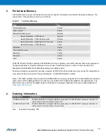
Страница 18: ...s a uniquely assigned ID for each ZigBit and owned by Atmel User of the ZigBit application can use this unique MAC ID to address the ZigBit in end applications The MAC ID can be read from the ZigBit using the Performance Analyzer Application that can be downloaded from www atmel com wireless 6 Ordering information Part number Description ATZB RF 212B 0 CN 900 MHz IEEE802 15 4 ZigBee OEM module bas...

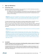
Страница 19: ...e marketed to OEM installers Use in portable exposure conditions FCC 2 1093 requires separate equipment authorization IMPORTANT Modifications not expressly approved by this company could void the user s authority to operate this equipment FCC section 15 21 IMPORTANT This equipment has been tested and found to comply with the limits for a Class A digital device pursuant to Part 15 of the FCC Rules ...

Страница 20: ... still responsible for testing their end product for any additional compliance requirements required with this module installed for example digital device emissions PC peripheral requirements etc This Module is labelled with its own IC ID If the IC ID Certification Number is not visible while installed inside another device then the device should display the label on it referring the enclosed modu...

Страница 21: ...Error Reference source not found ZigBit 900 MHz Wireless Modules 21 Appendix A Revision history Doc Rev Date Comments 0 1 16 Jul 13 Internal Initial release 0 5 24 Dec 13 Added more sections ...

Страница 22: ... the sale of Atmel products EXCEPT AS SET FORTH IN THE ATMEL TERMS AND CONDITIONS OF SALES LOCATED ON THE ATMEL WEBSITE ATMEL ASSUMES NO LIABILITY WHATSOEVER AND DISCLAIMS ANY EXPRESS IMPLIED OR STATUTORY WARRANTY RELATING TO ITS PRODUCTS INCLUDING BUT NOT LIMITED TO THE IMPLIED WARRANTY OF MERCHANTABILITY FITNESS FOR A PARTICULAR PURPOSE OR NON INFRINGEMENT IN NO EVENT SHALL ATMEL BE LIABLE FOR A...

Отзывы: