background image


Atmel AVR1923 

8394B-AVR-02/12 

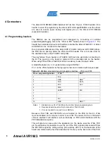
Table 4-4. 

Expansion header J3. 

Pin on J3 

Name on J3 

XMEGA pin 

Shared with onboard functionality 

PA0 PA0 Ligh

sensor 

(

1

)


PA1 PA1 Temperature 

sensor 

(

1

)


PA2 PA2 Filter 

output 

(

1

)


PA3 PA3 Display 

reset 

PB4 PB4 JTAG 

TMS 

PB5 PB5 JTAG 

TDI 

PB6 PB6 JTAG 

TCK 

PB7 PB7 JTAG 

TDO 

9 GND 

-  - 

10 VCC_P5V0 

-  - 

Note: 

1.  Can be disconnected from onboard functionality by cut-straps. 

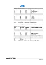
The header J4 offers digital communication interfaces such as UART and TWI but 
care must be taken because some pins are also connected to on-board peripherals. 

Table 4-5. 

Expansion header J4. 

Pin on J4 

Name on J4 

XMEGA pin 

Shared with onboard functionality 

1 SDA 

PE0 

2 SCL 

PE1 

3 RXD 

PE2 

4 TXD 

PE3 

SS 

PD0 

Display register select 

(1)


MOSI 

PD3 

Serial flash MOSI 

MISO 

PD2 

Display and serial flash MISO input 

SCK 

PD1 

Display and serial flash clock input 

9 GND 

-  - 

10 VCC_P3V3 

-  - 

Note: 

1.  Can be disconnected from onboard functionality by cut-strap (J204). 

Содержание AVR XMEGA-A3BU

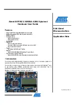
Страница 1: ...y Atmel AVR AT45DB642D DataFlash serial flash Footprints for external memory Atmel AVR AT25DF series industry standard serial flash 1 Introduction The Atmel AVR XMEGA A3BU Xplained evaluation kit is a...

Страница 2: ...the XMEGA USB DFU boot loaders Atmel AVR Studio 5 AVR Studio 5 is a free Atmel IDE for development of C C and assembler code for Atmel microcontrollers Atmel FLIP Flexible In system Programmer BatchI...

Страница 3: ...Embedded Workbench for Atmel AVR IAR Embedded Workbench is a commercial C C compiler that is available for 8 bit AVR There is a 30 day evaluation version as well as a 4k code size limited kick start v...

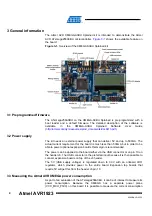
Страница 4: ...The actual current requirement for the board is much less than 500mA but in order to be able to power optional expansion boards this margin is recommended The power can be applied to the board either...

Страница 5: ...ng the jumper or an amperemeter mounted since this can cause latch up of the Atmel AVR ATxmega256A3BU due to current flow into the I O pins 3 4 Programming the kit The kit can be programmed either fro...

Страница 6: ...JTAGICE mkII it is necessary to use the squid cable A standoff adapter no 1 is needed when using AVR ONE Pin 1 on the JTAG header is at the top right corner and is marked with a square pad Table 4 1 X...

Страница 7: ...device or to mount the external pull ups on the available footprints R200 and R201 Please refer to the assembly drawing in the design documentation for the location of these footprints Table 4 2 Expan...

Страница 8: ...unctionality by cut straps The header J4 offers digital communication interfaces such as UART and TWI but care must be taken because some pins are also connected to on board peripherals Table 4 5 Expa...

Страница 9: ...1A SH AT45DB321D MWU AT25DF321A SH AT45DB161D SS AT25DF161 SH AT45DB081D SS AT25DF081 SSH AT45DB041D SS AT25DF021 SSH AT45DB021D SS AT45DB011D SS 5 2 Atmel AVR QTouch button The XMEGA A3BU Xplained ki...

Страница 10: ...are activated The yellow LEDs and the red LED can be activated by driving the connected I O line to GND The green LED is controlled via a FET and is by default on when the board is powered However th...

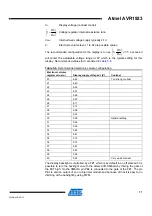
Страница 11: ...configuration Electronic volume register value Display supply voltage V0 V Contrast 20 6 44 Too strong contrast 21 6 40 22 6 35 23 6 31 24 6 26 25 6 22 26 6 17 27 6 13 28 6 08 29 6 03 30 5 99 Optimal...

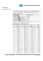
Страница 12: ...ce k Temp C NTC resistance k 30 2197 225 0 357 012 30 79 222 60 22 224 29 2055 558 1 338 006 31 75 675 61 21 374 28 1923 932 2 320 122 32 72 306 62 20 561 27 1801 573 3 303 287 33 69 104 63 19 782 26...

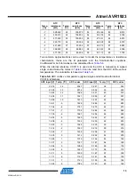
Страница 13: ...signed single ended mode the codes in Table 5 9 can be read from the ADC at the various temperatures The calculation is based on Table 5 8 Table 5 9 ADC codes vs temperature signed single ended mode w...

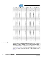
Страница 14: ...53 0 078 78 77 0 535 27 531 0 075 79 75 0 515 28 511 0 073 80 72 0 495 29 491 0 070 81 70 0 476 30 472 0 068 82 67 0 458 31 454 0 065 83 65 0 440 32 437 0 063 84 63 0 423 33 420 0 061 85 61 0 407 34 4...

Страница 15: ...ge across the series resistor of the sensor circuitry it is necessary to calculate the voltage based on the current U Ev x R x ICA 100 Based on the current and the illuminance the output voltage of th...

Страница 16: ...in Atmel AVR Studio 5 The AVR Software Framework can also be found as a separate package online at http www atmel com dyn products tools_card asp tool_id 4192 For more information about the code examp...

Страница 17: ...ode sticker on the back side of the board The first line on the sticker shows the product ID and the revision For example A09 1248 2 can be resolved to ID A09 1248 and revision 2 7 1 Revision 2 Revisi...

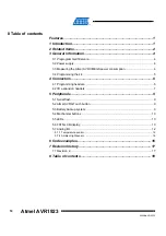
Страница 18: ...mption 4 3 4 Programming the kit 5 4 Connectors 6 4 1 Programming headers 6 4 2 I O expansion headers 7 5 Peripherals 9 5 1 Serial flash 9 5 2 Atmel AVR QTouch button 9 5 3 Battery backup system 9 5 4...

Страница 19: ...his document or in connection with the sale of Atmel products EXCEPT AS SET FORTH IN THE ATMEL TERMS AND CONDITIONS OF SALES LOCATED ON THE ATMEL WEBSITE ATMEL ASSUMES NO LIABILITY WHATSOEVER AND DISC...

Страница 20: ...Mouser Electronics Authorized Distributor Click to View Pricing Inventory Delivery Lifecycle Information Microchip ATXMEGAA3BU XPLD...

Отзывы: