


AT-OMNI-521
74
The Virtual Matrix
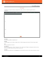
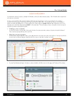
The illustration below, shows a multiple OmniStream units (encoders and decoders). The Virtual Matrix is organized
into rows and columns.
The blue circle with the checkmark indicates that these two OmniStream units are connected to one another.
The third column shows an OmniStream R-Type decoder (AT-OMNI-521). The fourth row shows an OmniStream
R-Type encoder (AT-OMNI-512). In this example, the source signal on
HDMI 1 IN
(encoder) is being sent out, over
the network, and will be displayed on
HDMI 1
on the decoder. This will create a
cross-connection
, which connects
both the encoder and decoder together.
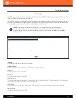
• Creating a cross-connection
To route an input on an encoder to an output, locate the row and column where an input and output intersect,
then click the square with the dots around it.
• Removing a cross-connection
To remove a
cross-connection
, click on the desired circle icon with the check mark symbol. The square with the
dots around it will be displayed indicating that the
cross-connection
has been removed.
• To view the individual streams for video, audio, and data, click the icons on the upper-left corner of the screen.
Layout and Operation
AT-OMNI-512
COLUMNS
ROWS
AT-OMNI-521
Cross-connection