Owner’s Manual
TSD-HF11
1x1 Paging Horn Crossover and
AtlasSound.com
– 5 –
Specifications are subject to change without notice.
1601 Jack McKay Blvd. • Ennis, Texas 75119 U.S.A.
Telephone: 800.876.3333 • Fax: 800.765.3435
6.
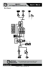
Input Limiter Control
- This control knob adjusts where the Limiter circuitry starts to reduce the
Output Level and must be carefully set. Rotate clockwise to make the limiter more sensitive
to input audio signals, thus reducing the Output levels. Rotate counterclockwise to reduce the
sensitivity, thus letting larger signal “Peaks” through to the output of the TSD-HF11. See also
“Limiter LED” in the previous section for setup instructions.
7.
Cable Management Retainer Points
- Use the rear panel screws for connecting the included cable
retainers. Each TSD comes with two cable retainers for simplified cable management.
8.
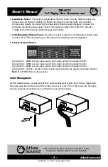
Function Selection Switch
Dip Switch # 1 - 200Hz Low Cut, place switch in the down position to activate the filter.
Dip Switch # 2 - 300Hz Low Cut, place switch in the down position to activate the filter.
Dip Switch # 3 - 400Hz Low Cut, place switch in the down position to activate the filter.
Dip Switch # 4 - All Pass - No Hi Cut filter is active when the switch is placed in the down position.
Note:
Hi Cut 15KHZ filter is always active.
Cable Management
All TSD models feature a simple but effective cable management system. Each TSD is shipped with
two cable wrap ties. Remove one of the screws on the rear of the TSD run the screw thru the cable
wrap tie head and resecure the screw. Wrap the tie around the cables.

