Owner’s Manual
TSD-HF11
1x1 Paging Horn Crossover and
AtlasSound.com
– 3 –
Specifications are subject to change without notice.
1601 Jack McKay Blvd. • Ennis, Texas 75119 U.S.A.
Telephone: 800.876.3333 • Fax: 800.765.3435
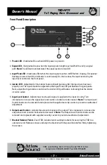
Front Panel Description
1.
Power LED
- Illuminates Blue when 24VDC power is present.
2.
Signal LED
- Illuminates Green when the input signal strength reaches 25mV to verify a signal
path.
Note:
The LED will not illuminate if the input level is turned Off.
3.
Input Peak LED
- Illuminates Red when the input signal reaches -3dBV before clipping. Occasional
flashing is normal but if this indicator is continuously On, then reduce the input level using the
input level control on the front panel.
4.
Limiter LED
- Adjustment of the Limiter feature should be done after the input gain has been
properly set. The input should be adjusted so the Input Peak LED just flashes on signal peaks.
Next, adjust the Input Limiter control so the Limiter LED just flashes, indicating that the limiter
circuit is active.
5.
Input Level Control
- Adjusts how much audio signal is applied to the input circuitry. Turn
clockwise to increase the signal level and counter-clockwise to decrease it.
Note:
The Input Level
Control knobs can be removed and replaced with supplied security covers to prevent unauthorized
adjustment.
6.
Output Level Control
- Adjusts the amount of signal at the output. Turn clockwise to increase the
output level and counter-clockwise to decrease it.
Note:
The Output Level Control knobs can be
removed and replaced with supplied security covers to prevent unauthorized adjustment.
7.
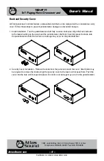
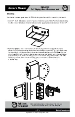
Bracket Retainer Points
- Each TSD includes two mounting brackets for securing the TSD to a
cabinet or wall. Remove screws and align the bracket with the panel hole before firmly tightening
the screws.
2
4
3
1
5
6
7
7
7
7

