Atlas BlueBridge BBWP Series Скачать руководство пользователя страница 8

8/8

AtlasSound.com

TELEPHONE: (800) 876-3333

FAX (800) 765-3435

BlueBridge BBWP-TOUCH7

7" Touch Panel DSP Wall Controller Installation Guide

1601 JACK MCKAY BLVD.  

ENNIS, TEXAS 75119  U.S.A.

©2013 Atlas Sound L

.P

.  All rights reserved.  Atlas Sound is a trademark of Atlas Sound L

.P

.  All other trademarks are the property of their respective owners.  All specs are subject to change without notice.  P/N 4938

57  A

TS004748 RevA 10/13  

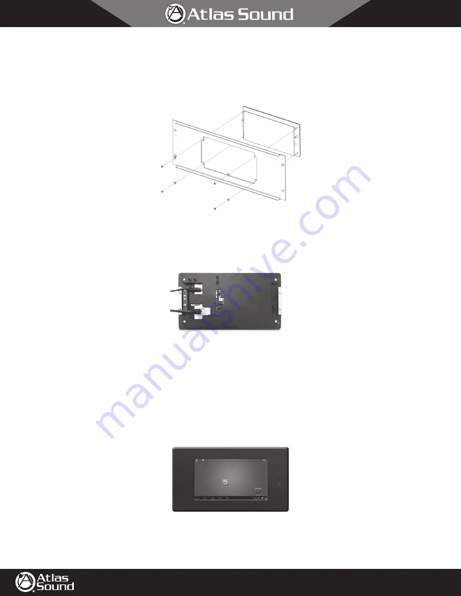
1.  Remove the surface mount back can from the TOUCH7 panel. On each side of the back can there are two M3 X 6 mm screws that must also be  
 removed. 

2.  Align the four studs of the TOUCH7 panel to the rack panel and secure to the panel using the four washers and nuts as shown in Figure 23.

3.  Chose the method to power the BBWP-TOUCH7. External 5V DC external power supply (included) or PoE switch.

4.  Make sure the PoE or external power supply is disconnected on the opposite end of the cable assuring NO DC power is present in the cables.

5.  Connect the DC Power and/or Ethernet CAT5e cable to the TOUCH7 as shown in Figure 24. 

6.  Place the assembly into the rack, carefully. Making sure no cables are pinched or kinked.

7.  Continue on to the "Powering Up" section.

Powering Up the BBWP-TOUCH7  

1.  Apply power to the cables whether using PoE or external DCV.

2.  Push the Power button and hold for 4 seconds. The screen will appear as in Figure 25. 

Note:

 The boot up home screen appearance may vary,  


but a lit up screen indicates that the BBWP-TOUCH7 is ready to associate or "map" to a BlueBridge system design. 

3.  Refer to the BlueBridge Wall Controller Guide for mapping the device and associating a BlueBridge control panel program. Refer to the BlueBridge  
 

Wall Control Reference Guide located at www.atlassound.com/bluebridge. 

Figure 23

Figure 24

Figure 25

Содержание BlueBridge BBWP Series

Страница 1: ...can be placed anywhere within a sound system as long as they are on the same network and connected using a CAT5e cable to a switch If the switch is a PoE type no external power to the BBWP is required...

Страница 2: ...ted on the opposite end of the cable ensuring no DC power is present in the cables 5 Run the cable s through the back can 6 Secure the back can to the surface using one of the screw slots provided 7 C...

Страница 3: ...BBWP TOUCH7 will be installed A Choose a location void of studs or conduit and where there is at least a 3 5 clearance behind the wall surface B Ensure the CAT5e cable can be routed to the chosen loca...

Страница 4: ...d finger tighten until the can is semi snug to the wall 6 There are two middle holes in the back can flanges to secure and align the can for visual straightness Note Be very careful because these hole...

Страница 5: ...gure 14 11 Insert and tighten the four lock washers and M3 nuts as shown in Figure 15 12 Chose the method to power the TOUCH7 A External 5V DC external power supply included B PoE network switch Using...

Страница 6: ...Up section on page 8 New Construction For new construction that has exposed wall studs the BBWP TOUCH7 can be mounted to the studs using a universal telescoping box bracket that must be purchased sepa...

Страница 7: ...r the cover bezel may not cover any cutting imperfections see Figure 20 E After the drywall is cutout to fit the in wall flanged back can secure the back can to the universal telescoping box bracket b...

Страница 8: ...supply included or PoE switch 4 Make sure the PoE or external power supply is disconnected on the opposite end of the cable assuring NO DC power is present in the cables 5 Connect the DC Power and or...

Отзывы: