S
PG
LV
P1
F1
0 0 0 0
H1 H2
H3 H4
H5 H6
H7 H8
N4
XAS136/186 Dd
16
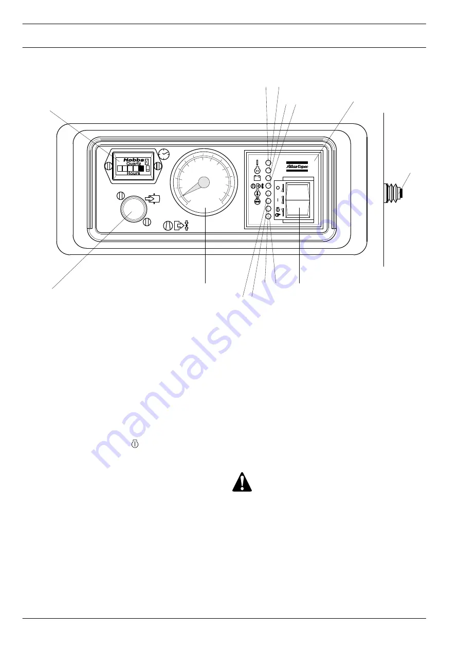
Fig. 3.8
Control panel
P1
Hourmeter
F1
Circuit breaker button
PG
Working pressure gauge
LV
Loading valve
N4
Control module
S
Start/Stop button
H1
LED (green) Fuel ON
H2
LED (green) Preheat (option)
H3
LED (red)
Charge indication
H4
LED (red)
Compressor outlet temperature
H5
LED (red)
Engine coolant temperature
H6
LED (red)
Engine oil pressure
H7
LED (red)
Spare 1
H8
LED (red)
Spare 2
3.3
S
TARTING
/S
TOPPING
Before starting, first operate the circuit breaker button (F1) at the
right side of the control panel (open right-hand service door first).
To start, the start/stop button (S) is switched to position ÓIÓ, the green
fuel ON lamp (H1), the red charge indication lamp (H3) and preheat
lamp (H2) go on (preheat lamp only, if Ócold startÓ option is
installed). After preheating, the preheat lamp goes out. When the
start/stop button is pushed in position Ó Ó, the starter motor will set
the engine in motion. Lamps H1 and H3 will go out as soon as the
engine has been started. After the start/stop button is released, it
automatically springs back to position ÓIÓ.
Run the engine a few minutes at no-load to warm up.
When the engine is running smoothly, press loading valve (LV) and
release as soon as pressure starts to build up.
Shutting down is simply done by pushing the start button in the Ó0Ó
position.
The control panel in addition indicates receiver pressure (PG) and
accumulated operating hours (P1).
Fault situations and protective devices (Also refer to Sect. 6
Problem Solving):
Ð
The starter motor is protected against prolonged starting or
against attempts to start when the group is already running.
(max. cranking time: 20 sec.)
Ð
A fault which occurs with the engine, either oil pressure too low,
coolant temperature (too high) or alternator voltage (too low) will
always and immediately cause the engine to cut out and one of
the control lamps H3, H5 or H6 to light up.
Ð
When the outlet temperature of the element becomes too high, a
thermocontact will also switch off the group immediately.
Control lamp H4 will light up.
Ð
The control lamps will remain on untill the group has been reset
(start button switched to position Ó0Ó).
3.4
D
URING OPERATION
The doors must be closed during operation and may be
opened for short periods only.
Regularly carry out following checks:
1. That regulating valve (RV) is correctly adjusted, i.e. starts
decreasing the engine speed when reaching the preset working
pressure in the receiver.
2. Check the air filter vacuum indicators (VI - Fig. 2.3). If the
yellow piston reaches the red marked service range, replace the
filter element. Reset the indicators by pushing the reset button.
3. On compressors with aftercooler, check that the automatic drain
of the water separator is operative without air leakage.
Содержание XA186 Dd
Страница 2: ...XAS136 186 Dd 2 ...


