background image

- 46 -

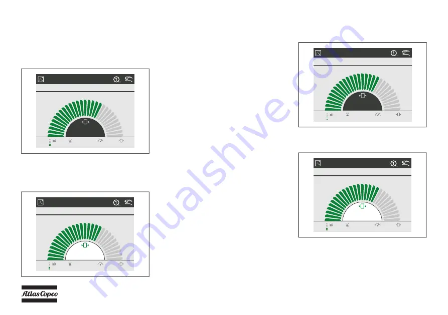
PRESSURE SETTING 

To  change  the  pressure  setting  there  are  two

possibilities.

1. Choosing between presets

The operator can choose between two preset 

pressures.

The current active preset is indicated in the top 

right corner of the display: 1 or 2. To switch to the 

other preset, go to the Main view and press the 

enter button for 2 seconds (the pressure set point 

will light up in green).

By pressing the left or the right arrow button the 

operator will be notified to:
“Press enter to go to other pressure setting X Y”
When enter is pressed the setting will become 

active.
By pressing enter again the controller will go out 

of edit mode.
The active preset pressure (1 or 2) will be visible 

in the top right corner of the display.

2. Changing the pressure of a preset

The operator can adjust the active preset as 

follows.

In the Main view when the operator presses the 

enter button for 2 sec. The pressure setting will 

light up in green when it is in edit mode.

By pressing the up and down buttons the pressure 

setting can be increased or decreased in 0.1 bar 

steps.
Pressing the enter button again confirms the 

pressure setting and will leave the edit mode.

MAIN VIEW

LOADED

7.2

1424RPM

7.2bar

1286h

40%

MAIN VIEW

LOADED

1424RPM

7.2bar

1286h

40%

7.2

MAIN VIEW

LOADED

7.2

1424RPM

7.2bar

1286h

40%

MAIN VIEW

LOADED

1424RPM

7.2bar

1286h

40%

7.2

Содержание U190 PACE KD WUX

Страница 1: ...Instruction Manual for Portable Compressors English U190 PACE KD WUX Engine Kubota V1505T ...

Страница 2: ......

Страница 3: ...ATLAS COPCO PORTABLE ENERGY DIVISION www atlascopco com Printed matter No 2960 1730 01 06 2019 Instruction Manual for Portable Compressors U190 PACE KD WUX Original instructions ...

Страница 4: ...turer s approval in writing Neglecting maintenance or making changes to the setup of the machine can result in major hazards including fire risk While every effort has been made to ensure that the information in this manual is correct Atlas Copco does not assume responsibility for possible errors Copyright 2019 Atlas Copco Wuxi Compressor Co Ltd Any unauthorized use or copying of the contents or a...

Страница 5: ...stem 22 3 2 Electric system 24 3 3 Wire harness 32 3 4 Markings and information labels 33 4 Operating instructions 34 4 1 lifting instructions 34 4 2 Starting Stopping 35 4 3 Before starting 35 4 4 Basic operation of the machine 36 4 4 1 Control panel 36 4 4 2 Overview icons 38 4 4 3 Possible views 40 4 4 4 Starting 42 4 4 5 Pressure setting 46 4 4 6 During operation 47 4 4 7 Stopping 47 4 4 8 Shu...

Страница 6: ... engine compressor 72 6 2 1 Servicing 72 6 2 2 Main parts 72 6 2 3 Cleaning the dust trap 72 6 2 4 Cleaning instructions filter element 72 6 2 5 Replacing the air filter element 73 6 2 6 Air receiver 74 6 3 Safety valve 74 6 4 Fuel system 74 6 4 1 Priming instructions 74 7 Problem solving 75 8 Available options 78 9 Technical specifications 79 9 1 Torque values 79 9 1 1 General torque values 79 9 ...

Страница 7: ...ponents Skill level 3 Electrical technician An electrical technician is trained and has the same qualifications as both the operator and the mechanical technician In addition the electrical technician may carry out electrical repairs within the various enclosures of the unit This includes work on live electrical components Skill level 4 Specialist from the manufacturer This is a skilled specialist...

Страница 8: ...equipment shall be kept clean i e as free as possible from oil dust or other deposits 7 To prevent an increase in working temperature inspect and clean heat transfer surfaces cooler fins intercoolers water jackets etc regularly See the Preventive maintenance schedule 8 All regulating and safety devices shall be maintained with due care to ensure that they function properly They may not be put out ...

Страница 9: ...tioned vertically the locking device must be applied and kept in good order 6 To lift heavy parts a hoist of ample capacity tested and approved according to local safety regulations shall be used 7 Lifting hooks eyes shackles etc shall never be bent and shall only have stress in line with their design load axis The capacity of a lifting device diminishes when the lifting force is applied at an ang...

Страница 10: ...ant or cleansing agent in or around the unit 14 All doors shall be shut during operation so as not to disturb the cooling air flow inside the bodywork and or render the silencing less effective A door should be kept open for a short period only e g for inspection or adjustment 15 Periodically carry out maintenance works according to the maintenance schedule 16 Stationary housing guards are provide...

Страница 11: ...speed during transport should be 20km h or less when traveling straight ahead and travel according to the road surface conditions 30 Be sure to fold up the caster before towing If you leave the caster down or drive on the caster there is a risk of serious accident or damage to the caster SAFETY DURING MAINTENANCE AND REPAIR Maintenance overhaul and repair work shall only be carried out by adequate...

Страница 12: ...es or sparks on a machine the surrounding components shall first be screened with non flammable material 17 Never use a light source with open flame for inspecting the interior of a machine 18 Disconnect battery clamp before starting electrical servicing or welding or turn battery switch in off position 19 When repair has been completed the machine shall be barred over at least one revolution for ...

Страница 13: ...above and in accordance with the technical specifications Safety reasons prohibit any other applications 3 National legislation requirements with respect to re inspection must be complied with 4 No welding or heat treatment of any kind is permitted to those vessel walls which are exposed to pressure 5 The vessel is provided and may only be used with the required safety equipment such as manometer ...

Страница 14: ...a continuous pneumatic regulating system and a blow off valve which is integrated in the unloader assembly The valve is closed during operation by air receiver pressure and opens by air receiver pressure via the compressor element when the compressor is stopped When air consumption increases the air receiver pressure will decrease and vice versa This receiver pressure variation is sensed by the re...

Страница 15: ...ith sound absorbing material Lifting eye A lifting eye is accessible from the roof of the unit Control panel The control panel grouping the air pressure gauge control switch etc is placed at the left hand rear end corner Data plate The compressor is furnished with a data plate showing the product code the unit serial number and the working pressure see chapter Data plate Serial number The serial n...

Страница 16: ... 16 Main Parts ...

Страница 17: ...compressor element DPoc Drain Plug compressor oil cooler DPosv Drain Plug oil shut off valve DSE Dip Stick Engine E Engine EP Exhaust Pipe F Fan FCc Filler Cap coolant FCft Filler Cap fuel tank FPco Filler Plug oil compressor element FT Fuel Tank IC Intercooler OFce Oil filter compressor element OFe Oil Filter engine OLG Oil Level Guage R Radiator Reference Name RV Regulating Valve SN Serial Numbe...

Страница 18: ... 18 COMPRESSOR REGULATING SYSTEM ...

Страница 19: ...eperator AOV Air Outlet Valve BV Bypass Valve CH Coupling Housing CE Compressor Element CP Control Panel F Cooling Fan DP Drain Plug E Engine OC Oil Cooler OSE Oil Seperator Element OSV Oil Stop Valve OFC Oil Filter Compressor SC Safety Cartridge SL Scavenge Line SV Safety Valve TS Temperature Sensor UA Unloader Assembly ...

Страница 20: ...mpressed air and oil pass into the air receiver oil separator AR OS The check valve CV prevents blow back of compressed air when the compressor is stopped In the air receiver oil separator AR OS most of the oil is removed from the air oil mixture The oil collects in the receiver and on the bottom of the separator element ...

Страница 21: ...or lubrication cooling and sealing is injected through holes in the gallery Lubrication of the bearings is ensured by oil injected into the bearing housings The injected oil mixed with the compressed air leaves the compressor element and re enters the air receiver where it is separated from the air as described in section Air flow The oil that collects on the bottom of the oil separator element is...

Страница 22: ... 22 CONTINUOUS PNEUMATIC REGULATING SYSTEM ...

Страница 23: ...m load speed and unloading speed the output of a screw compressor is proportional to the rotating speed 2 Air inlet throttling If the air consumption is equal to or exceeds the maximum air output the engine speed is held at maximum load speed and the throttle valve is fully open If the air consumption is less than the maximum air output air receiver pressure increases and the regulating valve supp...

Страница 24: ...trol Module Xc2003 PT1 f6 Pressure Sensor Inlet pressure PT2 f5 Pressure Sensor Vessel Pressure S0 d1 Battery Switch S2 b3 Emergency Stop TS1 f6 LP Element Temperature TS3 f6 AMBIENT Temperature Y1 f3 Loading Valve Y2 f3 EPRS Solenoid Valve K3 c6 EPRS Heater Relay R1 c6 EPRS Heater Relay MPU f3 MPU Sensor PS1 f4 Engine oil pressure TS2 f4 Engine Coolant Temperature Y3 b2 Fuel Solenoid Valve ...

Страница 25: ...Circuit diagram 9829 3801 45 Reference Grid Name F4 b9 Fuse F5 b9 Fuse G2 c9 Alternator K1 c8 Relay starter Motor K2 c8 Glow Relay K4 b8 Relay N2 b8 Can Actuator R2 b9 Grid Heater Y3 c9 Fuel Solenoid Valve M2 c9 Fuel pump ...

Страница 26: ... 26 Option circuit diagram 9829380198 01 15kva ...

Страница 27: ... 27 9829380198 02 15kva ...

Страница 28: ... 28 9829380198 03 15kva ...

Страница 29: ... 29 Option circuit diagram 9822108160 01 6kva ...

Страница 30: ... 30 9822108160 01 6kva ...

Страница 31: ... 31 9822108160 01 6kva ...

Страница 32: ... 32 WIRE HARNESS 1094 4377 02 ...

Страница 33: ...he instruction manual before starting Warning Part under pressure Do not stand on outlet valves Start Stop indication of switch Do not run the compressor with open doors Lifting permitted Use diesel fuel only Sound power level in accordance with Directive 2000 14 EC 84 533 EEC and 85 406 EEC expressed in dB A Fork lifting permitted Don t lift here Read the instruction manual before lifting E Fille...

Страница 34: ... way that the compressor which must be placed level is lifted vertically Keep lifting acceleration and retardation within safe limits The lifting eye 1 can be accessed from the roof of the unit The operator is expected to apply all relevant Safety precautions When lifting or transporting the compressor in any way the battery switch must always be in the OFF position Lifting acceleration and retard...

Страница 35: ...the fuel filters until clean fuel flows from the drain cock See section Priming instructions 6 Empty the dust trap of each air filter AF See section Cleaning the dust trap 7 Check coolant level in engine coolant top tank Top up if necessary Consult the Engine Operation Manual for coolant specifications 8 Attach the air line s to the closed air outlet valve s Connect the safety chain Safety precaut...

Страница 36: ...ration Mode via pressure sensor data from the customer s installation PC Operation Mode with software running on a PC In this section is described how to operate the machine in Local Operation Mode at the Operation Panel CONTROL PANEL Reference Name Power off on switch To switch the control panel on and off Start button Pressing this button will start the compressor Stop button Pressing this butto...

Страница 37: ...sing this button you can toggle between Measurements View and Main View Settings View button By pressing this button you can toggle between Settings View and Main View Alarms View button By pressing this button you can toggle between Alarms View and Main View Navigation buttons These buttons are used to navigate through the display menu s Enter button Confirms stores the selection change Back butt...

Страница 38: ...set and Active operation mode indication 2 Active compressor status 3 Navigation toggle between main view and engine view 4 Engine information 5 Vessel pressure indication or information text 6 Alarm indication and compressor information Main View Indication Measuring View Indication Settings View Indication Alarm View Indication ...

Страница 39: ... the Auto Start and Auto Stop function are both inactive Operation Mode Block Mode Reference Name Engine warning lamp amber LED steady on low alarm LED flashing slow medium alarm LED flashing fast high alarm Engine shutdown lamp red LED steady on low alarm LED flashing slow medium alarm LED flashing fast high alarm High exhaust system temperature LED steady on the diesel particulate filter is bein...

Страница 40: ...ata Active Sequence Vessel pressure Engine rpm Fuel level Running hours Alarm indication Operation mode Pre set indication Auto load indication Overhaul indication DPF indication Clock Fuel level Battery voltage Running hours Vessel pressure Regulating pressure Emergency stop count Loaded hours VUE PRINCIPALE COMPRESSEUR CHARGÉ 14 4 1700RÉGIME 18 28h 580L s VUE PRINCIPALE COMPRESSEUR CHARGÉ 1701RÉ...

Страница 41: ...re Engine oil temperature Engine inlet temperature Engine boost pressure Engine load Engine rpm Rpm setpoint Ambient temperature General Alarms Alarm Log DM1 List Event Log DM2 List ECU ГОТОВ К НАГРУЗКЕ 1399ОБ MNH 69Ч Расход топлива 4 л ч Температура охлаждающей жидкости двигателя 87 C Температура впускного воздуха двигателя 30 C Давление масла в двигателе 2 6 бар Давление топлива в двигателе 4 1 ...

Страница 42: ...hine is now ready to be started and is waiting for a start command The display will change to The engine electronics ECU will be powered up As soon as communication between compressor controller and engine controller is established the machine will preheat according to the parameters of the engine controller If the Power button is switched to switch off while the vessel is blowing down it will not...

Страница 43: ...t for some time Resting time depends on cranking time The display now shows After expiry of the engine resting time a new cranking sequence will start Max starting attemps is 10 Active Buttons Active Buttons VUE PRINCIPALE PRÉCHAUFFAGE MOTEUR 0 0 RÉGIME 0 0bar 40 1286h VUE PRINCIPALE DÉMARRAGE MOTEUR 324RÉGIME 0 0bar 40 1286h 800RÉGIME 324RÉGIME 0RÉGIME VUE PRINCIPALE MOTEUR AU REPOS 324RÉGIME 0 0...

Страница 44: ...ing up temperature is reached within 30 seconds the display will show After warming up the machine is ready to be loaded and is waiting for a load command the display shows Active Buttons VUE PRINCIPALE RÉCHAUFFAGE DU MOTEUR 1200RÉGIME 0 0bar 40 1286h 40 C 25 C 13 C 300s 76s 0s Active Buttons VUE PRINCIPALE RÉCHAUFFAGE DU MOTEUR 1200RÉGIME 2 7bar 40 1286h 30s 7s 0s VUE PRINCIPALE PRÊT À CHARGER 0 ...

Страница 45: ...lay will show The loading valve will be energized and pressure starts building up During loading the following display is shown default display The controller controls the speed of the engine in order to meet the requested working pressure at the most economical fuel usage Active Buttons Active Buttons MAIN VIEW BUILDING UP VESSEL PRESSURE 3 9 1200RPM 3 9bar 41 1286h Active Buttons VUE PRINCIPALE ...

Страница 46: ...tive By pressing enter again the controller will go out of edit mode The active preset pressure 1 or 2 will be visible in the top right corner of the display 2 Changing the pressure of a preset The operator can adjust the active preset as follows In the Main view when the operator presses the enter button for 2 sec The pressure setting will light up in green when it is in edit mode By pressing the...

Страница 47: ... the display will show After cooling down the engine will stop and the display will show The engine is stopped and the controller will do a double check to see if the engine is really stopped The doors must be closed during operation and may be opened for short periods only Be aware not to touch hot parts when the door is open When the engine is running the air outlet valves ball valves must alway...

Страница 48: ...rning level the alarm icon will automatically disappear As long as there is an alarm icon in the middle of the bottom part of the view all active acknowledged un acknowledged alarms can be seen by pressing the Alarm View button Pressing the Alarm View button again will bring you back to the Main View Set Clock Press the Settings View button scroll to 1000 GENERAL SETTINGS press Enter scroll to 129...

Страница 49: ...ange press Enter To change a setting the red figure is editable Scroll up down and press Enter to change Use left right to shift between editable figure Now press BACK until you re back in the Main View or in the menu you require Go To Diagnostics Press the Settings View button scroll to 1000 GENERAL SETTINGS press Enter scroll to 1150 DIAGNOSTICS Enter the DIAGNOSTICS menu Enter the ENABLE parame...

Страница 50: ...3050 VESSEL PRESSURE HIGH WARNING WARNING 3060 VESSEL PRESSURE HIGH SHUTDOWN SHUTDOWN 3450 BATTERY LOW ALARM INDICATION 3460 BATTERY HIGH ALARM WARNING 4000 LOW PRESSURE ELEMENT TEMP ALARM INDICATION 4050 AMBIENT TEMP ALARM 1 INDICATION 4060 AMBIENT TEMP ALARM 2 INDICATION 6190 CHARGE MONITORING WARNING 7010 ENGINE SPEED ALARM 1 SHUTDOWN 7020 ENGINE SPEED ALARM 2 SHUTDOWN 7030 ENGINE COOLANT TEMP ...

Страница 51: ...rminated by the emergency stop itself hardware as well as by the software When the emergency stop button 1 is pressed the operator can unlock the emergency stop by turning it counter clockwise The emergency stop button is only to be used in emergency situations not for stopping procedures ...

Страница 52: ...sumer is disconnected the engine goes on for 60 second before falling back to idle speed With the current continuously monitored a consumer having just been switched on is temporary disconnected from the generator to be re connected as soon as the engine reaches nominal speed This safety mechanism prevents load at too low speed Turning the generator switch 3 to position 0 cuts off the power from t...

Страница 53: ...nuine parts needed for normal maintenance of both compressor and engine Service Paks minimize downtime and keep your maintenance budget low Order Service Paks at your local Atlas Copco dealer SERVICE KITS A service kit is a collection of parts to fit a specific repair or rebuilding task It guarantees that all necessary parts are replaced at the same time which improves the uptime of the unit The o...

Страница 54: ...void any warranty claims Maintenance schedule running hours 50 hours after intial start up Every 250 hours Every 500 hours Every 1000 hours Every 1500 hours Yearly Biennially Service parts 3002 6085 20 3002 6085 30 3002 6085 40 3002 6085 50 For the most important subassemblies Atlas Copco has developed service kits that combine all wear parts These service kits offer you the benefits of genuine pa...

Страница 55: ...Analyse coolant 3 7 x x Replace fan belt x Adjust engine inlet and outlet valves 2 x Replace oil separator element x x Check Replace safety cartridge x x x Replace compressor oil filter s 4 x x x Change compressor oil 1 6 x x Replace air filter element 1 x x x Measure alternator insulation resistance on optional genset x Check electrolyte level and teminals of battery x Test safety valve 8 x Check...

Страница 56: ...filters mean fuel starvation and reduced engine performance 6 See section Oil specifications 7 The following part numbers can be ordered from Atlas Copco to check on inhibitors and freezing point 2913 0028 00 Refractometer 2913 0029 00 pH meter 8 See section Safety valve 9 Replace all rubber flexibles every 6 years according to DIN 20066 Keep the bolts of the housing the lifting beam tow bar and a...

Страница 57: ...leases excess heat efficiently whilst maintaining excellent bore polish protection to limit oil consumption PAROIL has an excellent Total Base Number TBN retention and more alkalinity to control acid formation PAROIL prevents soot build up PAROIL is optimized for the latest low emission EURO 3 2 EPA TIER II III engines running on low sulphur diesel for lower oil and fuel consumption PAROIL E xtra ...

Страница 58: ...ssor oil based on the ambient temperatures in the actual operating area Synthetic compressor oil PAROIL S Liter US gal Order number can 5 1 3 1630 0160 00 can 20 5 3 1630 0161 00 barrel 210 55 2 1630 0162 00 container 1000 265 1630 0163 00 ...

Страница 59: ...6 Synthetic engine oil PAROIL E Synthetic engine oil PAROIL E Xtra Liter US gal Order number can 5 1 3 1615 5953 00 can 20 5 3 1615 5954 00 barrel 210 55 2 1615 5955 00 container 1000 264 1 1630 0096 00 Liter US gal Order number can 5 1 3 1630 0135 01 can 20 5 3 1630 0136 01 barrel 210 55 2 1626 0102 00 ...

Страница 60: ...k engine oil level in accordance to the instructions in the Engine Operation Manual and if necessary top up with oil CHECK COMPRESSOR OIL LEVEL With the unit standing horizontal check the level of the compressor oil The oil level should be shown in the sight glass or above the sight glass Add oil if necessary Before removing the oil filler plug 2 ensure that the pressure is released by opening an ...

Страница 61: ...vant drain plugs Drain plugs are fitted at the air receiver DPar compressor element DPcv DPosv and compressor oil cooler DPoc Catch the oil in a drain pan Unscrew the filler plug 2 to speed up draining After draining reposition and tighten the drain plugs 3 Remove the oil filters 3 e g by means of a special tool Catch the oil in a drain pan 4 Clean the filter seat on the manifold taking care that ...

Страница 62: ...n released by opening the filler plug 2 one turn 2 Wait a few minutes until the oil level is constant oil level gauge 1 3 Remove the oil filler plug 2 and top up with oil until the pointer of the oil level gauge 1 is in the upper part of the green area 4 Reinstall and tighten the filler plug 2 ...

Страница 63: ...continue 5 Put in a new oil separator screw on new compressor oil filter s and close the oil vessel according to the instructions 6 Fill the oil vessel with the minimum amount of replacement oil run the compressor under light load conditions for 30 minutes 7 Thoroughly drain the system when the oil is warm leaving as little oil in the system as possible especially in dead areas if possible blow ou...

Страница 64: ...y to use Ethylene Glycol based coolant premixed in an optimum 50 50 dilution ratio for antifreeze protection guaranteed to 40 C 40 F Because PARCOOL EG inhibits corrosion deposit formation is minimized This effectively eliminates flow restriction problems through the engine coolant ducts and the radiator minimizing the risk of engine overheating and possible failure It reduces water pump seal wear...

Страница 65: ...COOLANT CHECK In order to guarantee the lifetime and quality of the product thus optimising engine protection regular coolant condition analysis is recommended The quality of the product can be determined by three parameters Visual check Verify the appearance of the coolant with regard to its colour and make sure that no loose particles are floating around pH measurement Check the pH value of the ...

Страница 66: ... level this quantity is to be filled without draining from the cooling system 1 Refractometer indication 20 C 4 F 33 2 Refractometer indication 22 C 7 6 F 3 Refractometer indication 25 C 13 F 4 Refractometer indication 30 C 22 F 5 Refractometer indication 36 C 32 8 F Engine coolant capacity liter Top up volume PARCOOL EG Concentrate without drainage Top up volume liter PN 1604 8159 00 Liter Vol Li...

Страница 67: ...se of expansion tank at normal level this quantity is to be drained from the cooling system 1 Refractometer indication 20 C 4 F 33 2 Refractometer indication 22 C 7 6 F 3 Refractometer indication 25 C 13 F 4 Refractometer indication 30 C 22 F 5 Refractometer indication 36 C 32 8 F Liter Vol Liter PARCOOL EG Concentrate PN 1604 8159 00 Engine coolant capacity liter Top up volume PARCOOL EG Concentr...

Страница 68: ...rn off the engine and allow to cool From theAtlas Copco Instruction book determine the amount of PARCOOL EG required Mix concentrate and water before filling Fill with a maximum rate of 10 l min 0 35 cu ft min Recheck coolant level and add coolant mixture if necessary CLEANING COOLERS Keep the compressor oil cooler and engine liquid cooler clean to maintain the cooling efficiency Clean by air jet ...

Страница 69: ...er charging a battery always check the electrolyte level in each cell if required top up with distilled water only When charging batteries each cell must be open i e plugs and or cover removed Preferably use the slow charging method and adjust the charge current according to the following rule of thumb battery capacity in Ah divided by 20 gives safe charging current in Amp MAKE UP DISTILLED WATER ...

Страница 70: ...y covered with petroleum jelly Carry out periodic condition tests Test intervals of 1 to 3 months depending on climate and operating conditions are recommended If doubtful conditions are noticed or malfunctions arise keep in mind that the cause may be in the electrical system e g loose terminals voltage regulator maladjusted poor performance of compressor etc COMPRESSOR ELEMENT OVERHAUL When a com...

Страница 71: ...sed by turning the adjusting wheel clockwise and anti clockwise respectively To adjust the normal working pressure proceed as follows 1 Loosen the lock nut of the regulating valve 2 Release Regulating Valve turn out 3 With the outlet valves AOV closed adjust the regulating valve RV until a pressure is reached of nominal pressure 1 5 bar 22 psi 4 Lock the regulating valve RV by fixing the lock nut ...

Страница 72: ...NS FILTER ELEMENT If element cleaning can not be avoided care should be taken that the filter element 4 is not washed out Please note that engine damage can cause considerable costs which makes the cost of a new filter element seam insignificant Safety cartridges 3 can not be cleaned but must be exchanged Please note that a cleaned element will never match the service life and performance of a new...

Страница 73: ...it and there will be a danger of damage to the engine Carefully clean the inside of the housing and put the element in the housing see section Replacing the air filter element New elements must also be inspected for tears or punctures before installation Discard the element 4 when damaged A dirty safety cartridge 3 is an indication of a mal functioning air filter element In that case replace the e...

Страница 74: ...r Prime the fuel system in order to purge trapped air The fuel system should be primed under the following conditions Compressor is put in operation for the first time Running out of fuel Storage Replacement of the fuel filter Daily drain condensate All adjustments or repairs are to be done by an authorized representative of the valve supplier see section General safety precautions Fuel leaked or ...

Страница 75: ... an Atlas Copco Service representative Blow down valve stuck in open position Check and correct as necessary Loading valve LV leaking past O ring With compressor running at max load speed disconnect hose leading to unloader If air leaks from the hose remove and inspect loading valve Replace damaged or worn O rings Oil separator element clogged Have element removed and inspected by an Atlas Copco S...

Страница 76: ...ews first remove the short screws then release the spring tension unscrewing the long ones Minimum pressure valve malfunctioning Remove and inspect valve Blow off valve malfunctioning Remove and inspect valve Possible faults Corrective actions Engine oil pressure too low Refer to the engine instruction manual Compressor or engine overheating See corrective actions Compressor overheating Fuel tank ...

Страница 77: ...nt compressor cooling Locate compressor away from walls when banked with other compressors leave space between them Oil cooler clogged externally Clean oil cooler Refer to section Cleaning coolers Oil cooler clogged internally Consult Atlas Copco Oil filters clogged Replace oil filters Oil level too low Check oil level Top up with recommended oil if necessary Thermostatic by pass valve remains stu...

Страница 78: ...lable options 1 Cold start 20 C 2 Aftercooler water separator bypass 3 Generator 15kVA 4 Inlet shut down spark arrestor 5 Tool box 6 Non return valve 7 Additional fuel filter 8 Lubricator 9 Additional fuel tank ...

Страница 79: ...4 10 21 M8 34 25 23 M10 70 52 24 M12 120 89 25 M14 195 144 23 M16 315 233 23 Assemblies Torque value Nm lbf ft Compressor to frame Bolts elements gear casing 46 33 95 Bolts elements support 80 59 04 Bolts support buffer 205 151 29 Bolts buffer frame 80 59 04 Engine to frame Bolts engine support 205 151 29 Bolts support buffer 46 33 95 Bolts buffer frame 23 16 97 Lifting beams to frame Bolts liftin...

Страница 80: ...umidity 0 Air inlet temperature C 20 F 68 Normal effective working pressure bar 10 5 psi 152 3 Designation Unit U190 PACE Minimum effective receiver pressure bar 3 psi 43 5 Maximum effective receiver pressure compressor unloaded bar 11 5 psi 166 7 Maximum ambient temperature at sea level 5 C 50 F 122 Minimum starting temperature C 10 F 14 Minimum starting temperature with coldstart equipment C 20 ...

Страница 81: ... 5 bar g r min 2200 Engine shaft speed compressor unloaded r min 1600 Free air delivery 2 6 At pressure setting 5 bar g l s 90 cfm 190 At pressure setting 7 bar g l s 90 cfm 190 At pressure setting 10 5 bar g l s 42 cfm 90 Fuel consumption at 100 FAD kg h 8 52 lb h 18 78 at 75 FAD kg h 7 lb h 15 43 at 50 FAD kg h 5 27 lb h 11 61 at 25 FAD kg h 3 59 lb h 7 91 at unload kg h 2 69 lb h 5 93 ...

Страница 82: ...sed air mg m 5 Engine oil consumption maximum g h NA Compressed air temperature at outlet valves 7 C 90 F 194 Noise level Sound pressure level Lp measured according to under free field conditions at 7 m distance dB A 73 Sound power level Lw complies with 2000 14 EC dB A 98 Designation Unit U190 PACE ...

Страница 83: ...1 Output according to SAE J 1995 at normal shaft speed kW 32 5 BHP 43 58 Load factor NA Capacity of oil sump Initial fill l 5 5 us gallon 1 45 Refill max 1 l 6 7 us gallon 1 76 Designation Unit U190 PACE Capacity of cooling system l 8 5 us gallon 2 24 Designation Unit U190 PACE Capacity of compressor oil system l 9 us gallon 2 37 Net capacity of air receiver l 18 us gallon 4 7 Capacity of fuel tan...

Страница 84: ... required for engine and compressor cooling combustion and for compression 4 With filter change 5 With after cooler 5 C 6 With after cooler 1 7 Without after cooler Tolerance 5 25l s FAD 250l s 4 250l s FAD The international standard ISO 1217 corresponds to following national standards British BSI 1571 part 1 German DIN 1945 Part 1 Swedish SS ISO 1217 American ANSI PTC9 ...

Страница 85: ... 85 Data plate 1 Name of the manufacturer 2 Vehicle identification number 3 Model 4 Unit serial number 5 Working pressure 6 Engine power 7 Speed 8 Manufacturing year ...

Страница 86: ...ng in the future is foreseen DISPOSAL OF MATERIALS Dispose of contaminated substances and material separately in accordance with locally applicable environmental legislation Before dismantling a machine at the end of its operating lifetime drain and dispose of all fluids of according the applicable local disposal regulations Remove the batteries Do not throw batteries into the fire explosion risk ...

Страница 87: ...n Engine oil drain 1874 Frame drain Vessel drain Fuel filling cap 488 73 Rain cap 20 30 2x 52 52 800 330 60 300 155 230 Frame drain plug 3x Frame water drain 2x 510 810 Service Panel 110 110 298 100 Air Inlet Air Inlet Hot Air Out 629 627 Air Inlet 1044 5 Xz 160 170 283 285 120 82 52 5 220 245 27 5 107 5 245 442 Xy 920 Xx Lifting hole 73 145 727 92 468 5 691 Service plate for Vessel Service plate ...

Страница 88: ... 416 5 R756 3 1388 268 5 1080 2744 831 5 1280 950 1135 973 50 If non service side placed near wall please keep more than mm distance Air Inlet Air Inlet Hot Air Out 693 892 Air Inlet 670 1080 442 2642 567 5 567 5 476 1176 970 ...

Страница 89: ... 89 Maintenance Log Compressor Customer Serial number Service hours Maintenance action Date By initials ...

Страница 90: ... 90 ...

Страница 91: ......

Страница 92: ......

Отзывы: