


Industrial Air Division
2920 5997 03
6
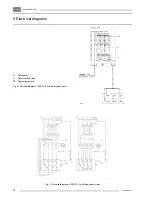
e1.
Motor overload relay
M.
Motor
PSR19.
Air pressure switch
S1-I.
Start button
S1-O.
Stop button
Y1.
Loading solenoid
valve
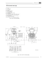
1.
Air intake silencer
2.
Air filter
3.
Oil filler pipe (not on
LEN)
4.
Crankcase breather
5.
Cooling fan
6.
Temperature reducer
7.
Finned discharge
collector
8.
LP cylinder(s)
9.
Oil level sight-glass
or crankcase
breather on LEN
10.
Oil drain plug/flexible
or crankcase
breather on LEN
11.
Check valve
assembly
13.
Check valve
14.
Air pressure gauge
15.
Safety valve
16.
Air receiver
17.
Air outlet valve
18.
Manual drain cock
(not on Pack unit)
20.
Pressure release
valve
22.
Temperature reducer
23.
Intercooler
24.
HP cylinder
25.
Relief valve
26.
Pulsation damper
28.
Muffler, unloading air
29.
Unloader
30.
Unloader plunger
31.
Piston ring
33.
Spring
34.
Unloader valve
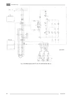
Figs. 2. Air flow and regulating systems
Fig. 2b. Air flow of LT and regulating system of LE/LT7 up to -12, LE7N and LE9N
Fig. 2a. Air flow of LE(N) and regulating system of LE/LT5 and -6
Содержание LE11
Страница 20: ...IndustrialAirDivision 2920 5997 03 20 Fig 13 Electrical diagram of LE LT7 up to 12 and LEN with transformer ...
Страница 22: ...IndustrialAirDivision 2920 5997 03 22 Fig 15 LE7 7N 8 8C LT7 8 730 Power Pack ...
Страница 23: ...IndustrialAirDivision 23 2920 5997 03 Fig 16 LE9 9N 11 12 LT9 11 12 930 1230 Power Pack ...
Страница 24: ...IndustrialAirDivision 2920 5997 03 24 Fig 17 LE5 6 6C LT5 6 Complete Unit ...
Страница 25: ...IndustrialAirDivision 25 2920 5997 03 Fig 18 LE7 7N 8 8C LT7 8 Complete Unit ...
Страница 26: ...IndustrialAirDivision 2920 5997 03 26 Fig 19 LE9 9N 11 12 LT9 11 12 Complete Unit ...
Страница 27: ...IndustrialAirDivision 27 2920 5997 03 Fig 20 LE LT7 8 9 11 12 Complete Unit with optional silencing hood ...
Страница 28: ...IndustrialAirDivision 2920 5997 03 28 Fig 21 LE LT7 8 9 11 12 Pack ...


