background image

Industrial Air Division

5

2920 5997 03

Fig. 1c. LE6, complete unit

Fig. 1e. LT8 Pack

Fig. 1d. LE7, complete unit

F1751

1

2

3

4

M
5

6
7

8

9

17

S1-1
S1-0

PSR19

S2

15
14
13
12

11

10

F1752

16

S1

PSR19

12

13
Y1

15

10

1 2 3 18

4

M

P1 19

17
23
22

6

21

20

9

F1750

Содержание LE11

Страница 1: ... 930 1230 LE7N LE9N LE LT7 8 9 11 12Pack IndustrialAirDivision B 2610Wilrijk Belgium Replaces No 2920599702 1994 12 This instruction book meets the requirements for instructions specified by the machinery directive 89 392 EEC and is valid for CE as well as non CE labelled machines ...

Страница 2: ...mention the type and the serial number shown on the data plate For all data not mentioned in the text see sections Preventive maintenance schedule and Principal data The company reserves the right to make changes without prior notice Page 5 Servicing and adjustment procedures 10 5 1 Unloader or check valve 10 5 2 Valves 10 5 3 Air filter 12 5 4 Setting of the air pressure switch 12 5 4 1 Air press...

Страница 3: ...e motor starter have the same regulating system as described in section 1 3 1 1 1 Generaldescription LE LEN and LT are two cylinder air cooled single acting piston compressors LE and LEN are single stage compressors LT are two stage compressors LEN are oil less compressors delivering oil free air LE and LEN are built for effective working pressures up to 10 bar LT5 up to 12 are built for effective...

Страница 4: ...ondensate drain cock 11 Oil drain plug 12 Safety valve 13 Air pressure gauge 14 Pressure release valve 15 Air outlet valve 16 Label electrical diagram 17 Fan guard 18 Crankcase breather 19 Motorstarter 20 Transport brackets must be removed 21 Hose compressed air from check valve to air receiver 22 Unloader 23 Muffler 24 HP cylinder head 25 Temperature reducer 26 Pulsation damper 27 Relief valve 28...

Страница 5: ...5 2920 5997 03 Fig 1c LE6 complete unit Fig 1e LT8 Pack Fig 1d LE7 complete unit F1751 1 2 3 4 M 5 6 7 8 9 17 S1 1 S1 0 PSR19 S2 15 14 13 12 11 10 F1752 16 S1 PSR19 12 13 Y1 15 10 1 2 3 18 4 M P1 19 17 23 22 6 21 20 9 F1750 ...

Страница 6: ... plug flexible or crankcase breather on LEN 11 Check valve assembly 13 Check valve 14 Air pressure gauge 15 Safety valve 16 Air receiver 17 Air outlet valve 18 Manual drain cock not on Pack unit 20 Pressure release valve 22 Temperature reducer 23 Intercooler 24 HP cylinder 25 Relief valve 26 Pulsation damper 28 Muffler unloading air 29 Unloader 30 Unloader plunger 31 Piston ring 33 Spring 34 Unloa...

Страница 7: ... of the inert type in each phase In case the overload protection is not supplied with the unit a circuit breaker instead of an isolating switch and fuses must be installed For LE LT7 up to 12 and LEN connect the power supply to terminals L1 L2 and L3 of line contactor K1 Fig 3 Connect the earth conductor to connector PE and the neutral conductor if provided to connector N on the terminal strip For...

Страница 8: ...ssure when the power becomes live again Safety precautions The operator must apply all relevant safety precautions including those mentioned in this book 3 1 Initial start up 1 Remove the transport brackets 20 Fig 1d and wooden blocks under compressor and motor feet 2 Check the electrical installation which must be in accordance with the instructions given in section 2 1 3 Check the setting of the...

Страница 9: ...g 4 700 On LE LT5 6 replace air filter 5 3 4 2 Fig 4 1000 Change muffler element on LE LT7 up to 12 and LEN 2 Fig 4 1000 Check tension of transmission belt s if equipped with 5 2000 Change oil if mineral oil is used not on LEN 4 2 2000 Inspect for carbon deposits in air receiver clean if necessary 2 yearly 3000 Change oil if Atlas Copco approved P A O oil is used not on LEN 4 2 5 Fig 4 3000 to Cha...

Страница 10: ... 3 Fig 4 5 2 Valves A faulty valve must be replaced immediately A faulty valve can be discovered as stated in section 6 points 1 and 4 It is highly recommended to replace the valves and gaskets each time the cylinder heads are disassembled because a new position of old valves results in accelerated wear Replacement of valve disks Figs 5 LE5 9 LE11 LE LT12 LT5 11 LP LT5 11HP Operation sequence LE7N...

Страница 11: ...joint 4 Cylinder 5 O ring 6 Inlet valve disk 7 Valve seat 8 Outlet valve disk 9 Outlet valve guard 10 Spiral spring 11 Cylinder head cover 12 Rubber cord joint 13 O ring 14 Inlet cap 15 Outlet cap 16 1 Pin 1 Outlet valve guard with central pin as drawn in Fig 5b only on LE9 11 12 and on low pressure side of LT9 11 12 Figs 5 Cylinder head valve assemblies Fig 5a LE5 to 9 LE7N and low pressure side ...

Страница 12: ...nd starting pressures i e to increase the starting pressure Turn the knob anti clockwise to increase the pressure difference The adjustment range is shown in the diagrams Figs 7 5 4 2 Air pressure switch MDR4 Fig 8 The maximum pressure is controlled by adjusting screw 2 Turn the screw clockwise to raise the maximum or stopping pressure anti clockwise to lower it The pressure difference is adjusted...

Страница 13: ...e hose or pipe to the closed air outlet valve Switching on pressure bar e Switching on pressure bar e Switching on pressure bar e LE5 6 Switching off pressure bar e LT530 up to 1230 Switching off pressure bar e LT5 6 Switching off pressure bar e Example LE5 6 Stopping pressure 7 bar e Starting pressure adjustable between 3 1 and 5 4 bar e Example LT5 6 Stopping pressure 16 bar e Starting pressure ...

Страница 14: ...ve h 2 Unloader plunger jammed or unloader valve or spring broken h Inspect unloader and replace parts where necessary i 2 Solenoid valve out of order i Remove and check valve Replace if necessary 2 Unit does not speed up a Voltage drop at motor terminals a Consult power supplier Change to larger cross section cable if necessary b 1 Pressure release valve of air pressure switch malfunctioning b Ch...

Страница 15: ... rated motor current have compressor inspected if currents are not equal have motor inspected Notes 1 only LE LT5 6 2 not for LE LT5 6 3 only LT 4 not for LEN d See 1i e 2 Muffler choked e Replace muffler element 3 Air receiver pressure rises above maximum and causes safety valve to blow a Air pressure switch incorrectly set or out of order a Set switch to unload compressor at rated maximum pressu...

Страница 16: ...1500 LT5 2 17 2 70 20 3 17 3 8 1 5 1 8 1500 1800 1 60 LT6 3 07 3 63 20 4 82 5 78 2 2 2 64 1500 1800 1 60 LT7 5 63 6 78 20 8 58 10 3 4 4 8 1500 1800 2 80 LT7 Pack 5 63 6 78 20 8 58 10 3 4 4 8 1500 1800 2 80 LT8 7 68 9 12 20 11 9 14 3 5 5 6 6 1500 1800 2 80 LT8 Pack 7 68 9 12 20 11 9 14 3 5 5 6 6 1500 1800 2 80 LT9 10 2 11 9 20 16 6 19 9 7 5 9 1500 1800 5 10 LT9 Pack 10 2 11 9 20 16 6 19 9 7 5 9 150...

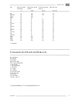
Страница 17: ...1 2 LT9 Pack 40 21 6 5 1 2 LT11 40 21 6 5 1 2 LT11Pack 40 21 6 5 1 2 LT12 40 21 6 5 1 2 LT12 Pack 40 21 6 5 1 2 LT530 40 31 5 6 5 1 2 LT730 40 31 5 6 5 1 2 LT930 40 31 5 6 5 1 2 LT1230 40 31 5 6 5 1 2 1 Direct drive 8 Conversion list of SI units into British units 1 bar 14 504 psi 1 g 0 035 oz 1 kg 2 205 lb 1 km h 0 621 mile h 1 kW 1 341 hp UK and US 1 l 0 264 US gal 1 l 0 220 Imp gal UK 1 l 0 035...

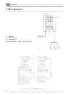
Страница 18: ...n 2920 5997 03 18 Fig 11 Electrical diagrams of LE LT5 6 with three phase motor D Setting dial e1 Motor overload relay S2 Air pressure switch Fig 10 Electrical diagram of LE LT5 6 with monophase motor 9 Electricaldiagrams ...

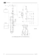
Страница 19: ...Compressor motor PSR19 Air pressure switch P1 Hourmeter S1 Selector switch 1 2 AUTO O AUTO TSHH11 Temperature switch notprovided T1 Transformer 1X1 2 Terminal strips 1X3 Plug Y1 Solenoid valve Figs 12 and 13 Electrical diagrams of LE LT7 up to 12 and LEN Fig 12 Electrical diagram of LE LT7 up to 12 and LEN without transformer ...

Страница 20: ...IndustrialAirDivision 2920 5997 03 20 Fig 13 Electrical diagram of LE LT7 up to 12 and LEN with transformer ...

Страница 21: ...ry Pg 16 8 Electric cable entry Pg 21 on rear side 9 Cooling air outlet 10 Air receiver must not be bolted on the floor without rubber pads 11 Shown LE7 8 with 250 l EURO receiver and silencing hood 12 Female air outlet G 1 2 13 Compressor cooling air and air inlet 14 Hole 15 x 24 4 x can be used for fixing without rubber pads Fig 14 LE5 6 6C LT5 6 530 Power Pack Figs 14 up to 21 Dimension drawing...

Страница 22: ...IndustrialAirDivision 2920 5997 03 22 Fig 15 LE7 7N 8 8C LT7 8 730 Power Pack ...

Страница 23: ...IndustrialAirDivision 23 2920 5997 03 Fig 16 LE9 9N 11 12 LT9 11 12 930 1230 Power Pack ...

Страница 24: ...IndustrialAirDivision 2920 5997 03 24 Fig 17 LE5 6 6C LT5 6 Complete Unit ...

Страница 25: ...IndustrialAirDivision 25 2920 5997 03 Fig 18 LE7 7N 8 8C LT7 8 Complete Unit ...

Страница 26: ...IndustrialAirDivision 2920 5997 03 26 Fig 19 LE9 9N 11 12 LT9 11 12 Complete Unit ...

Страница 27: ...IndustrialAirDivision 27 2920 5997 03 Fig 20 LE LT7 8 9 11 12 Complete Unit with optional silencing hood ...

Страница 28: ...IndustrialAirDivision 2920 5997 03 28 Fig 21 LE LT7 8 9 11 12 Pack ...

Отзывы: