background image

9.  

Fault finding

Table 24 Fault finding

Condition

Pump does not start up

 on page 112

Pump gets too hot

 on page 112

Motor power consumption is too high

 on page 113

Pump is too loud

 on page 114

Pump is losing lubricant

 on page 114

Oil gets too dark

 on page 114

Lubricant in the pump chamber

 on page 115

Pump does not attain its pumping speed

 on page 115

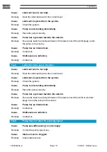
Fault

Pump does not start up

Cause

Motor incorrectly connected.

Remedy

Connect motor correctly.

Cause

Overtemperature switch or motor stator defective.

Remedy

Contact us.

Cause

Motor rotor defective.

Remedy

Contact us.

Cause

Pump has seized
- defective rotors, bearings or toothed gears
- pump restarted when it is still hot.

Remedy

Wait for 60 minutes and restart the pump again. If the pump does not start,
contact us.

Fault

Pump gets too hot

Cause

Cooling water supply is not sufficient.

Remedy

Make sure that the cooling water supply is sufficient.

Cause

Cooling water lines are clogged.

Remedy

Decalcify cooling water lines.

Cause

Ambient temperature is too high or cooling air flow is obstructed.

Remedy

Install the pump at a suitable place or ensure a sufficient flow of cooling air.

Cause

Pump is operating in the wrong pressure range.

Remedy

Check the pressure levels within the system.

Fault finding

07/2021 - ©Atlas Copco

Page 112

1950840208_A

Содержание DWS 450 VSD+

Страница 1: ...Dry Screw Vacuum Pump DWS VSD INSTRUCTION MANUAL 1950840208_A Original instructions ...

Страница 2: ...egistered trademark of DuPont E I du Pont de Nemours and Company Loctite is a registered trademark of Henkel Corporation Natural Blue is a registered trademark of Henkel Corporation Disclaimer The content of this manual may change from time to time without notice We accept no liability for any errors that may appear in this manual nor do we make any expressed or implied warranties regarding the co...

Страница 3: ...awing 18 3 5 Purge data 20 3 6 Electrical data 22 3 6 1 Electrical connections 23 3 7 Cooling water data 25 3 8 DP clean high flow purge solvent flush option 26 4 Elektronikon graphic controller 28 4 1 Introduction 28 4 2 Control panel 30 4 3 Icons used 31 4 4 Main screen 33 4 4 1 Function 33 4 4 2 Two and four value lines screens 34 4 4 3 Chart views 35 4 4 4 Selection of a main screen view 36 4 ...

Страница 4: ... gas supply 89 6 7 1 Flammable pyrophoric materials 90 6 7 2 Gas purges 90 6 8 Leak test the dry pumping system 91 6 9 Electrical supply 92 6 9 1 Mains supply cable connection 93 6 9 2 EMC filter 94 6 10 Connect and set up the cooling water 96 6 11 Install the accessories 98 6 12 Commission the dry pumping system 98 6 13 Install additional safety equipment 99 6 14 Purge gas set up 99 6 15 High flo...

Страница 5: ...9 8 5 1 Checking the oil levels and refilling 109 8 5 2 Inspect the connections pipelines cables and fittings 110 8 6 Overhaul 111 9 Fault finding 112 9 1 Converter fault codes 116 9 2 Faults 116 10 Storage 128 11 Disposal 129 12 Service 130 12 1 Return the equipment or components for service 130 13 Spares and accessories 131 Legal declarations 132 07 2021 Atlas Copco Page 5 1950840208_A ...

Страница 6: ...screen 2 value lines 34 Figure 12 Typical Main screen 4 value lines 34 Figure 13 Typical Main screen 4 value lines 36 Figure 14 Example of Event History screen 53 Figure 15 Installation drawing DWS 750 VSD 80 Figure 16 Installation drawing DWS 450 VSD 81 Figure 17 Service diagram 85 Figure 18 Connecting the pump inlet 89 Figure 19 Interspool connections on the pump 92 Figure 20 EMC filter switch l...

Страница 7: ...nance of the device please contact our nearest subsidiary Important safety information is highlighted as warning and caution instructions Obey these instructions WARNING If you do not obey a warning there is a risk of injury or death Different symbols are used according to the type of hazard CAUTION If you do not obey a caution there is a risk of minor injury damage to equipment related equipment ...

Страница 8: ...wledge in the fields of mechanics electrical engineering pollution abatement and vacuum technology and personnel specially trained for the operation of vacuum pumps Safety and compliance 07 2021 Atlas Copco Page 8 1950840208_A ...

Страница 9: ...oltages Warning Heavy object Identifies a possible hazard from a heavy object Warning Hot surfaces Identifies a potential hazard from a hot surface 45o MAX Warning Maximum angle of paired slings The maximum angle of the paired slings must not be more than 45 Warning Moving parts present Identifies parts that move You must let the parts that turn stop be fore you remove the electrical power Warning...

Страница 10: ...tion The dry pumping systems range has been developed to meet the demanding requirements for process pumping solutions in industrial applications The range sets new standards for harsh process capability reliability and reduced cost of ownership in low footprint packages The dry pumping system is designed as a plug and play system Connect the dry pumping system correctly provide the power and set ...

Страница 11: ...cess inlet 2 Floor mounting hole 4 off 1 Process inlet 2 Floor mounting hole 4 off Figure 2 Front view DWS 450 VSD 1 Process inlet 2 Floor mounting hole 4 off 1 Process inlet 2 Floor mounting hole 4 off 07 2021 Atlas Copco Page 11 1950840208_A Introduction ...

Страница 12: ... gas ballast 0 80 slm MV2 7 Gas inlet 8 Exhaust outlet 9 Mains power inlet 10 Communication cable 1 Cooling water inlet 2 HV seal purge valve MV3 3 Spare gas port 4 Cooling water outlet 5 Manual valve gas ballast 0 50 slm MV1 6 Manual valve gas ballast 0 80 slm MV2 7 Gas inlet 8 Exhaust outlet 9 Mains power inlet 10 Communication cable Introduction 07 2021 Atlas Copco Page 12 1950840208_A ...

Страница 13: ...e gas ballast 0 50 slm MV1 6 Manual valve gas ballast 0 80 slm MV2 7 Gas inlet 8 Exhaust outlet 9 Mains power inlet 10 Communication cable 2 4 3 GENIUS Instant Insights option The GENIUS BOX can be provided as an option for the DWS VSD pump The GENIUS BOX can be mounted in the electrical cabinet The GENIUS BOX allows the read out of parameters of the pump on a user login protected web site https g...

Страница 14: ...US BOX close to other electronic equipment which may also cause interference if the equipment is inadequately protected Observe warning signs and manufacturer recommendations The operator must maintain a distance of at least 20 cm 8 inches during GENIUS BOX operation Do not operate the GENIUS BOX in areas where the use of cellular modems are not advisable without proper device certifications These...

Страница 15: ... Materials in con tact with the proc ess gas Pump shaft and rotors Cast SG iron Seals PTFE and fluoroelastomer Gas system Carbon steel brass PTFE and fluoroelastomer Degree of protec tion Hazardous electrical sub system IP21D IEC60529 Lubrication Oil type PFPE Drynert 25 6 recommen ded Fomblin 25 6 alternative Krytox 1525 alternative Table 2 General technical data Characteristics DWS 750 VSD DWS 4...

Страница 16: ...e data Pump Characteristics Typical peak pumping speed Ultimate shaft seal purge only Maximum continuous inlet pressure Units m3 h cfm mbar mbar DWS 750 VSD 740 436 1 x 10 2 1000 DWS 450 VSD 450 265 1 x 10 2 1000 Speed may be limited 3 3 Loading data Refer to Installation drawings on page 80 for the centre of gravity positions for dry pumping systems The loading data in Table Loading data is for d...

Страница 17: ...Figure 5 Levelling foot loads DWS 750 VSD Figure 6 Levelling foot loads DWS 450 VSD 07 2021 Atlas Copco Page 17 1950840208_A Technical data ...

Страница 18: ...ng access 14 Emergency stop button 15 Adapter standard 16 Adapter standard Adapter with bellow optional 1 Process inlet 2 Cooling water inlet 3 Spare gas ports 4 Cooling water outlet 5 Gas inlet 6 Exhaust outlet 7 Cooling air outlet 8 Cooling air inlet area cubicle 9 Controller 10 Smart box Genius box Antenna position optional 11 Communication cable 12 Mains power inlet 13 Motor cranking access 14...

Страница 19: ...4 Emergency stop button 15 Adapter standard 16 Adapter standard Adapter with bellow optional 1 Process inlet 2 Cooling water inlet 3 Spare gas ports 4 Cooling water outlet 5 Gas inlet 6 Exhaust outlet 7 Cooling air outlet 8 Cooling air inlet area cubicle 9 Controller 10 Smart box Genius box Antenna position optional 11 Communication cable 12 Mains power inlet 13 Motor cranking access 14 Emergency ...

Страница 20: ...aracteristics Rating Units Purge gas supply pressure range 2 5 6 9 bar gauge 36 100 psi gauge Purge gas supply quality ISO 8573 Class 2 Purge gas inlet connection 1 2 inch BSP female Technical data 07 2021 Atlas Copco Page 20 1950840208_A ...

Страница 21: ... 2 off 6 0 01 6 0 12 MV 1 on MV 2 off 6 0 01 6 0 50 12 62 MV 1 off MV 2 on 6 0 01 6 0 80 12 92 MV 1 on MV 2 on 6 0 01 6 0 130 12 142 MV 3 position b MV 1 off MV 2 off 6 6 0 01 0 12 MV 1 on MV 2 off 6 6 0 01 0 50 12 62 MV 1 off MV 2 on 6 6 0 01 0 80 12 92 MV 1 on MV 2 on 6 6 0 01 0 130 12 142 The dry pumping systems in a standard configuration must run with a seal purge If the purge free kit is equ...

Страница 22: ...onnector for 380 460 V sys tems UT16 UT16 PE The maximum geometric wire gauge for UT16 and UT16 PE is 25 mm2 and maximum AWG size is 4 AWG Table 8 General electrical data Description Rating Units Supply voltage 3 phase 380 460 see rating plate V a c Frequency 50 60 Hz Wiring configuration 3 wire plus Earth ground Voltage tolerance range 10 Installation category II IEC 60664 1 Input supply voltage ...

Страница 23: ...ou use the machines controlled by a frequency converter The safety precautions depend on the type of network used TN TT IT system Contact us for more information Most pumps are designed for use in TT TN networks and are intended for an industrial environment where the electrical supply is separated from the residential commercial supply network To use the pump in light industrial commercial or res...

Страница 24: ...m the control panel It also accepts the start and stop command signals from the Clock function if programmed and set to on Remote control The pump accepts the command signals from the external switches remote control It also accepts the command signals from the emergency stop start and stop command signals from the clock function LAN control The pump is controlled through a local network Contact u...

Страница 25: ...cle size 0 2 mm2 Acidity 7 0 to 10 5 pH Hardness 250 ppm of CaCO3 250 mg of CaCO3 per litre Total Dissolved Solids TDS 1500 mg l Total Suspended Solids TSS 10 mg l Specific conductivity 2000 mS cm Materials in contact with the cool ing water Stainless steel Nitrile PTFE brass polyamide and fluoroelastomer Water inlet connection G3 8 inch BSP female Water outlet connection G3 8 inch BSP female Maxi...

Страница 26: ... SLM 29 psi dP 15 SLM 17 4 psi dP 12 SLM 14 5 psi dP 86 15 SLM 17 4 psi dP 15 SLM 17 4 psi dP 12 SLM 14 5 psi dP 68 12 SLM 14 5 psi dP 12 SLM 14 5 psi dP 12 SLM 14 5 psi dP DWS 450 VSD 104 15 SLM 26 1 psi dP 12 SLM 21 7 psi dP 10 SLM 14 5 psi dP 86 12 SLM 21 7 psi dP 12 SLM 21 7 psi dP 10 SLM 14 5 psi dP 68 10 SLM 14 5 psi dP 10 SLM 14 5 psi dP 10 SLM 14 5 psi dP 3 8 DP clean high flow purge solve...

Страница 27: ...rge air filter 1 2 inch NPT male available as a spare refer to Table Spares DP clean solvent flush fluid inlet connection 3 8 inch BSP male DP clean solvent suc tion pipe connection 3 8 inch BSP female Note The DP clean solvent suction pipe is supplied with the pump but not fitted Refer to the instruction given with the kit to activate the function 07 2021 Atlas Copco Page 27 1950840208_A Technica...

Страница 28: ...to decrease the power consumption restarts the pump automatically when the pressure decreases The high water handling capability pumps have a purge cycle The purge cycle stops and removes condensed water from the sealing oil Note A number of time based automatic start stop command can be programmed A start command will be executed if programmed and activated even after manually stopping the pump P...

Страница 29: ...time interval service interval All the service operations must be done before the end of the service interval If the service interval elapses and a service operation are not done a message will be shown on the display to do the applicable service operations Automatic Restart After Voltage Failure ARAVF WARNING AUTOMATIC RESTART OF THE PUMP Risk of injury If the automatic operation mode in the cont...

Страница 30: ...tically controls the pump 8 Voltage on LED Shows that the voltage is switched on 9 Pictograph Voltage on 10 Enter key To select the parameter shown by a horizontal ar row Only the parameters followed by an arrow that point to the right can be changed 11 Escape key To go to previous screen or to end the current ac tion 12 Scroll keys Keys to move through the menu 13 Stop button To stop the pump Aut...

Страница 31: ...ng vacuum control Machine control mode Local start or stop Remote start or stop Network control ARAVF ARAVF is active Week timer Week timer is active Active protection functions Emergency stop Shutdown Warning Service Service is necessary Main screen display Value lines display icon Chart display icon General icons No communication network fault Not valid 07 2021 Atlas Copco Page 31 1950840208_A E...

Страница 32: ... Table 16 System icons Icon Description Pump element Fan Frequency converter Motor Network problem General alarm Inputs Outputs Alarms warnings shutdown Counters Test Settings Service Saved data Access key User password Elektronikon graphic controller 07 2021 Atlas Copco Page 32 1950840208_A ...

Страница 33: ...2 Enter key 3 Escape key 4 4 1 Function The main screen is shown when the voltage is set to on and one of the key is pushed The main screen is automatically set to off when no keys are pushed for some minutes Refer to Figure Control panel The five main screen views that can be selected are Two value lines Four value lines 07 2021 Atlas Copco Page 33 1950840208_A Elektronikon graphic controller ...

Страница 34: ...cal Main screen 4 value lines 1 Inlet Pressure 2 Flow 3 Element Body Temperature 4 Off Shutdown 5 Menu 6 Vacuum control purge preparing to go online 1 Inlet Pressure 2 Flow 3 Element Body Temperature 4 Off Shutdown 5 Menu 6 Vacuum control purge preparing to go online Text changes upon the pump s actual condition Section A shows the information about the pump operation for example the inlet pressur...

Страница 35: ...verload a service message or the emergency stop to have access to all the data collected by the controller The function of the action buttons is related to the displayed menu The most used functions are Designation Function Menu To go to the menu Modify To change the programmable settings Reset To reset a timer or message To select an action button use the Scroll keys and push the Enter key To go ...

Страница 36: ... the control icons line refer to value lines display icon or chart display icon in Icons used on page 31 and push the Enter key A screen similar to the one that follows is shown Select the necessary layout and push the Enter key Refer to Inputs menu on page 37 4 5 Calling up menus When the voltage is switched on the main screen is automatically shown Figure 13 Typical Main screen 4 value lines To ...

Страница 37: ...enu icon inputs Function To display the value of the measured data analog inputs and the status of the digital inputs for example emergency stop contact motor overload relay etc To select the digital input to be shown on the chart on the Main screen Procedure Start from the Main screen refer to Main screen on page 33 Use the Scroll keys to move the cursor to the Menu action button Push the Enter k...

Страница 38: ...mergency Stop 5 Overload Motor 1 1 Inputs 2 Inlet Pressure 3 Element Body Temperature 4 Emergency Stop 5 Overload Motor 1 The screen shows a list of all the inputs with their related icon and readings If an input has a warning or shutdown the initial icon is replaced by the applicable warning or shutdown for example the Stop icon or the Warning icon shown in the screen above Elektronikon graphic c...

Страница 39: ...ht grey background in above screen push the Enter key on the controller A screen almost the same as the one below is shown The first item in the list is selected in this example Inlet Pressure To change the selection push the Enter key again A pop up window opens Push the Enter key again to remove this input from the chart Another pop up window opens confirmation 07 2021 Atlas Copco Page 39 195084...

Страница 40: ...lect Yes to remove or No to stop the step In almost the same way a different input signal can be selected as the Main Chart Signal Elektronikon graphic controller 07 2021 Atlas Copco Page 40 1950840208_A ...

Страница 41: ...en refer to Main screen on page 33 Use the Scroll keys to move the cursor to the Menu action button Push the Enter key The screen that follows is displayed 1 Menu 2 Regulation 1 Menu 2 Regulation Use the Scroll keys to move the cursor to the outputs icon refer to menu icon Push the Enter key The screen that follows is displayed 07 2021 Atlas Copco Page 41 1950840208_A Elektronikon graphic controll...

Страница 42: ...itial icon is replaced by the related warning or shutdown 4 8 Counters Menu icon counters Function To show the running hours the number of motors starts the number of hours that the regulator has been powered up the fan starts the emergency stops Procedure Start from the Main screen refer to Main screen on page 33 Use the Scroll keys to move the cursor to the Menu action button Push the Enter key ...

Страница 43: ...1 Counters 2 Running Hours 3 Motor Starts 4 Load Relay 5 VSD 1 20 RPM In the percentage of the time that the motor speed was between 1 and 20 The screen shows a list of all counters with their readings 4 9 Control mode selection Function To select the control mode for the pump The control modes are as follows Local control Remote control Local Area Network LAN control 07 2021 Atlas Copco Page 43 1...

Страница 44: ...s selected Use the Scroll keys to move the cursor to the regulation icon Push the Enter key The regulation screen shows the three control modes as follows Local control Remote control LAN control Elektronikon graphic controller 07 2021 Atlas Copco Page 44 1950840208_A ...

Страница 45: ...l mode Push the Enter key on the controller The selected control mode is shown on the Main screen Refer to Icons used on page 31 for the meaning of the icons 07 2021 Atlas Copco Page 45 1950840208_A Elektronikon graphic controller ...

Страница 46: ...programmed service intervals Procedure Start from the Main screen refer to Main screen on page 33 Use the Scroll keys to move the cursor to the Menu action button Push the Enter key The screen that follows is shown Use the Scroll keys to move the cursor to the Service icon refer to Menu icon Push the Enter key The screen that follows is shown Elektronikon graphic controller 07 2021 Atlas Copco Pag...

Страница 47: ...g Hours 3 Real Time hours 4 Reset Example for service level A The figures at the left are the programmed service intervals For the service interval A the programmed number of running hours is 4000 hours upper row and the programmed number of real time hours is 8760 hours which corresponds to one year second row This means that the controller will launch a service warning when 4000 running hours or...

Страница 48: ... be shown on the screen After the service actions related to the shown levels are completed the timers must be reset From the Service menu select Service Plan Push the Enter key The screen that follows is shown 1 Service Plan 2 Level 3 Running Hours 4 Real Time Hours 5 Modify 1 Service Plan 2 Level 3 Running Hours 4 Real Time Hours 5 Modify Modifying a service plan Depending on the operating condi...

Страница 49: ...Change the value as necessary using the or key Push the Enter key to confirm Note Running hours can be changed in steps of 100 hours Real time hours can be changed in steps of 1 hour 07 2021 Atlas Copco Page 49 1950840208_A Elektronikon graphic controller ...

Страница 50: ...vice action for example Service level Running hours or Real time hours use the Scroll keys to select the action and push the Enter key 4 11 Modifying the setpoint Menu icon setpoint Function On the pumps with a frequency converter driven main motor two different setpoints can be programmed You can use this menu to select the active setpoint Procedure Start from the Main screen refer to Main screen...

Страница 51: ...2 5 Indirect Stop Level 2 6 Modify 1 Regulation 2 Setpoint 1 3 Indirect Stop Level 1 4 Setpoint 2 5 Indirect Stop Level 2 6 Modify The screen shows the settings To change the settings use the Scroll keys to move the cursor to the Modify action button Push the Enter key The screen that follows is shown 07 2021 Atlas Copco Page 51 1950840208_A Elektronikon graphic controller ...

Страница 52: ...re set Indirect stop setpoint setpoint minus Indirect stop level The motor will decelerate to minimum speed and the inlet valve will close The settings indirect stop level and direct stop level are programmable refer to Programmable settings on page 75 4 12 Event history menu Menu icon Event History Function To view the last shutdown and last emergency stop data Procedure Start from the Main scree...

Страница 53: ... screen Use the Scroll keys to move the cursor to the necessary shutdown or emergency stop Push the Enter key to view the date time and status of the pump when the selected shutdown or emergency stop occurred 4 13 Modifying general settings Menu icon Settings Function To display and change different settings 07 2021 Atlas Copco Page 53 1950840208_A Elektronikon graphic controller ...

Страница 54: ...the Settings icon refer to the Menu icon Push the Enter key The screen that follows is shown The screen shows different icons By default the User Password icon is selected The status bar shows the description related to the selected icon Each icon covers one or more items such as Access level Elements Fan Converters Motor Starter General ARAVF Network Elektronikon graphic controller 07 2021 Atlas ...

Страница 55: ...l keys to select the Modify button and push the Enter key A screen same as the above is displayed The first item Language is selected Use the â Scroll key to select the setting to be changed and push the Enter key A pop up screen is displayed Use the Scroll keys to select the necessary item and push the Enter key In the setting menu you can adjust Runtime at minimum pressure Pre purge time Post pu...

Страница 56: ...et pressure band Four different week schemes can be programmed A week cycle can be programmed A week cycle is a sequence of 10 weeks For each week in the cycle you can select one of the four programmed week schemes Note In the controller you can select different timers on one day up to eight actions It is not possible to programme two actions at the same time Keep minimum of 1 minute difference be...

Страница 57: ...ning Time 1 Week Timer 2 Week Action Schemes 3 Week Cycle 4 Status 5 Week Timer Inactive 6 Remaining Running Time The first item in this list is highlighted in red Select the necessary item Push the Enter key to change the value Programming week schemes Select Week action schemes and push the Enter key A new window is displayed The first item in the list is highlighted in red Push the Enter key to...

Страница 58: ...iday 7 Saturday 8 Sunday A new window is displayed The Modify action button is selected Push the Enter key to create an action 1 Monday 2 Modify 1 Monday 2 Modify A new pop up window is displayed Use the Scroll keys to move the cursor to the necessary action from the list Push the Enter key Elektronikon graphic controller 07 2021 Atlas Copco Page 58 1950840208_A ...

Страница 59: ...dify A new window is displayed The action is visible in the first day of the week 1 Monday 2 Start 3 Save 4 Modify 1 Monday 2 Start 3 Save 4 Modify A pop up window is displayed Use the á or â Scroll keys to change the hours Use the ß or à Scroll keys to select the minutes 07 2021 Atlas Copco Page 59 1950840208_A Elektronikon graphic controller ...

Страница 60: ... the cursor to the necessary actions Push the Enter key 1 Monday 2 Are you sure 3 No 4 Yes 5 Save 6 Modify 1 Monday 2 Are you sure 3 No 4 Yes 5 Save 6 Modify Push the Escape key to exit the window The action is shown below the day the action is planned Elektronikon graphic controller 07 2021 Atlas Copco Page 60 1950840208_A ...

Страница 61: ...e is a sequence of 10 weeks For each week in the cycle you can choose one of the four programmed week schemes Select the Week Cycle from the main Week Timer menu list 1 Week Timer 2 Week Action Schemes 3 Week Cycle 4 Status 5 Week Timer Inactive 6 Remaining Running Time 1 Week Timer 2 Week Action Schemes 3 Week Cycle 4 Status 5 Week Timer Inactive 6 Remaining Running Time A list of 10 weeks is dis...

Страница 62: ... Week Action Scheme 1 1 Week Cycle 2 Week 1 3 Week Action Scheme 1 4 Week Action Scheme 2 5 Week Action Scheme 3 6 Modify 1 Week Cycle 2 Week 1 3 Week Action Scheme 1 4 Week Action Scheme 2 5 Week Action Scheme 3 6 Modify Check the status of the Week Timer Use the Escape key to go back to the main Week Timer menu Select the status of the Week Timer Elektronikon graphic controller 07 2021 Atlas Cop...

Страница 63: ...k Timer Inactive 6 Remaining Running Time A new window is displayed Select Week 1 to set the Week Timer active 1 Week Timer 2 Week 3 Week Timer Inactive 4 Week 1 1 Week Timer 2 Week 3 Week Timer Inactive 4 Week 1 Push the Escape key to exit the window The status shows that the week 1 is active 07 2021 Atlas Copco Page 63 1950840208_A Elektronikon graphic controller ...

Страница 64: ...ing Time from the list Push the Enter key to change the value 1 Week Timer 2 Week Action Schemes 3 Week Cycle 4 Status 5 Remaining Running Time 1 Week Timer 2 Week Action Schemes 3 Week Cycle 4 Status 5 Remaining Running Time This timer is used when the week timer is set and the pump must continue to operate for example 1 hour This timer is before the Week Timer action Elektronikon graphic control...

Страница 65: ... possible for unauthorised persons to change the setting Procedure Start from the Main screen refer to Main screen on page 33 Use the Scroll keys to move the cursor to Menu action button Push the Enter key The screen that follows is shown Use the Scroll keys to move the cursor to the Settings icon refer to Modifying general settings on page 53 07 2021 Atlas Copco Page 65 1950840208_A Elektronikon ...

Страница 66: ...nstead of the display of the controller If the pump has a SMARTBOX the network connection of the controller is already in use To let the web server function the network cable must be unplugged from the SMARTBOX and replaced by the cable of the company network If the web sever and the SMARTBOX are necessary at the same time contact the local customer centre Configure a dedicated PC connection Make ...

Страница 67: ... and Sharing Centre Click Change adapter settings Select the Local Area connection which is connected to the controller Click with the right button and select properties 07 2021 Atlas Copco Page 67 1950840208_A Elektronikon graphic controller ...

Страница 68: ...rties that are checked After selecting TCP IPv4 click on the properties button to change the settings Use the settings as follows IP Address 192 168 100 200 Sub netmask 255 255 255 0 Click ok and close the network connections Elektronikon graphic controller 07 2021 Atlas Copco Page 68 1950840208_A ...

Страница 69: ... reserved for the controller Get the correct Gateway and Subnet mask settings For example IP 10 25 43 200 Gateway 10 25 42 250 Subnet mask 255 255 254 0 Connect controller to the company s network LAN with a UTP cable min CAT 5e Adapt the network settings in the controller Go to Main Menu 07 2021 Atlas Copco Page 69 1950840208_A Elektronikon graphic controller ...

Страница 70: ... Go to Settings Go to Network Go to Ethernet Elektronikon graphic controller 07 2021 Atlas Copco Page 70 1950840208_A ...

Страница 71: ... change the settings Adapt the IP address Adapt the Gateway address Adapt the Subnet mask Set the Ethernet communication to on Wait until the LAN network connects to the controller 07 2021 Atlas Copco Page 71 1950840208_A Elektronikon graphic controller ...

Страница 72: ...P address of the controller you want to view in your browser In this example http 192 168 100 100 The interface opens Navigation options The banner shows the pump type and the language selector In this example three languages are installed on the controller The navigation menu is on the left side of the interface If a licence is for ESi is foreseen the menu contains 3 buttons Pump shows all pump s...

Страница 73: ...uts Analog inputs show the pump units These units can be changed in the preference button from the navigation menu Counters Counters give an overview of all the actual counters from controller and pump Info Status Machine status is always shown on the web interface Digital Inputs Gives an overview of all Digital inputs and status 07 2021 Atlas Copco Page 73 1950840208_A Elektronikon graphic contro...

Страница 74: ...es an overview of all special protections of the pump Service Plan Shows all levels of the service plan and status This screen only shows the running hours It is possible to show the actual status of the service interval Elektronikon graphic controller 07 2021 Atlas Copco Page 74 1950840208_A ...

Страница 75: ... 35 Maximum post purge time min 0 30 180 Manual purge time min 0 2 120 ES post purge time min 0 30 180 Table 20 Protections Parameter Unit Minimum setting Warning Shutdown Maximum setting Vacuum pump element body temperature shut down warn ing level C 111 120 130 140 F 231 8 248 266 284 4 18 1 Service plan The built in service timers will give a service warning message after their respective pre p...

Страница 76: ...ngs that are not consistent For example if the warn ing level is programmed at 120 C 248 F the minimum limit for the shutdown level changes to 121 C 250 F The recommended difference between the warning level and shutdown level is 10 C 18 F Delay at signal Time period during which the warning signal must exist before the warning message is shown Delay at start The time period after starting which m...

Страница 77: ...seal all vacuum inlet and outlet ports to prevent possible oil leakage Ensure that the dry pumping system is correctly labelled if in doubt contact us Follow the procedure laid out in Storage on page 128 and then read form HS1 and fill out form HS2 which can be found at the back of this manual 07 2021 Atlas Copco Page 77 1950840208_A Transportation ...

Страница 78: ...mping system Users can be trained by us to conduct the tasks described in this manual contact us or your local service centre for more information Do not remove the temporary cover or blanking plate from the dry pumping system inlet and exhaust until ready to connect the dry pumping system to the vacuum or exhaust extraction system Do not operate the dry pumping system unless the inlet and exhaust...

Страница 79: ...cables hoses and pipework during installation to avoid the possible risk of trips Before locating the dry pumping system ensure that the installation area is clean and free from debris and contamination such as oil For the dry pumping system to perform to specification appropriate facilities must be provided as detailed in this manual Before installing we recommend that you read the publication P6...

Страница 80: ...6 1 Installation drawings Figure 15 Installation drawing DWS 750 VSD A Inlet valve assembly B Utility side A Inlet valve assembly B Utility side Installation 07 2021 Atlas Copco Page 80 1950840208_A ...

Страница 81: ... dry pumping system WARNING Suitable lifting equipment must be used to move the dry pumping system It is too heavy to lift by hand Move the dry pumping system to its operating position using any of the following methods Use a forklift or pallet truck to lift the dry pumping system 07 2021 Atlas Copco Page 81 1950840208_A Installation ...

Страница 82: ... and is not damaged The pump must be level to a maximum of 3 degrees in any direction measured at the pump inlet It can be located directly on the floor or a frame Guidance for the access areas general and service is given in the installation drawings Pumps are provided with four floor mounting holes at the bottom of the base frame refer to Front view on page 11 If necessary fit shims which must b...

Страница 83: ...reate a significant pressure drop A rule of thumb on single pump installations maintain the diameter of the pump inlet as far into the process as possible Do not install the vacuum pump such that it will cause strain on the inlet or outlet flanges or any connecting pipework Refer to Installation drawings on page 80 Water cooling piping must be at least equal to or larger than its nominal diameter ...

Страница 84: ... The inlet control valve and blow off solenoid are pressure controlled To operate they need to be connected to a compressed air source The pump is supplied with a push in coupling for nylon tube diameter 8 x 6 mm 1 Valve pressure connection 1 Valve pressure connection Note Effectively isolate the machine from all sources of overpressure and make sure that the pump system is at atmospheric pressure...

Страница 85: ...basis Condensation in the air supply should be minimized 6 4 Lubrication The dry pumping systems are given a charge of oil before leaving the factory 6 5 Electrical connections Figure 17 Service diagram Note You can find the electrical diagram in the electric cabinet Description Refer to Dimension drawing on page 18 for the correct position of the electrical connection 1 Give an isolating switch 2...

Страница 86: ...s the command signals from the emergency stop start and stop command signals from the clock function LAN control The pump is controlled through a local network contact us Note Modifications must be approved by us Stop the pump and switch off the voltage before external equipment is connected Only potential free contacts are permitted Pump status indication The controller has a potential free auxil...

Страница 87: ... sufficient conductance to ensure the exhaust pressure limit is not normally exceeded CAUTION Use a catchpot to prevent the drainage of condensate back into the dry pumping system Condensate that drains back into the dry pumping system could damage the pump Do not reuse any O ring or O ring assembly and do not allow debris to get into the dry pumping system during installation When connecting the ...

Страница 88: ...aned regularly as part of routine maintenance Accumulation of dust in the exhaust line can reduce conductance and therefore increase exhaust pressure which may damage the pump The frequency of exhaust line cleaning depends on the process On very dusty applications use a low impedance inlet filter to reduce maintenance requirements 1 Referring to Figure Connecting the pump inlet remove the temporar...

Страница 89: ...e able to be isolated for lockout tagout purposes CAUTION Ensure that the purge gas supply conforms to the requirements given in the Technical data on page 15 Failure to do so may cause the gas pipelines to become blocked or the dry pumping system to be damaged Refer to Side view on page 12 for the location of the purge gas connection Nitrogen and clean dry air are suitable purge gases for the dry...

Страница 90: ...ests that the following measures will reduce the risks of pumping flammable mixtures and pyrophoric materials but it is your responsibility to carry out a risk assessment and take appropriate measures Do not allow air to enter the equipment Ensure that the dry pumping system is leak tight Ensure that gases in the pump do not enter the flammable range This may be achieved by diluting gases in the p...

Страница 91: ...ould occur For example if a mass flow controller is being used to supply flammable gases to the process assume a flow rate for flammable gases that could arise if the mass flow controller is fully open Continually measure the inert gas flow rate If the flow rate falls below that required then the flow of flammable gases or vapours to the pump must be stopped 6 8 Leak test the dry pumping system WA...

Страница 92: ... be connected to a suitably fused and protected electrical supply and a suitable earth ground point WARNING The pump will restart automatically when the electrical supply is restored after an electrical supply failure To prevent the automatic restart the pump must be connected to the electrical supply through suitable control equipment which must be reset manually after an electrical supply failur...

Страница 93: ...ified on the rating plate contact us The dry pumping system is protected from motor overloads and short circuits by solid state electronics The power wiring between the dry pumping system and the electrical installation must be protected When selecting input fuses refer to Electrical data on page 22 Pump rating information can be found on the label on the rear of the pump To connect the electrical...

Страница 94: ... damage to the equipment Ground the neutral point on the power supply to comply with the EMC directive before turning on the EMC filter CAUTION DRIVE DAMAGE Risk of drive damage When using a drive with a non grounding network high resistance grounding or asymmetric grounding network place the screw for the EMC filter switch in the OFF position and disable the built in EMC filter Failure to comply ...

Страница 95: ...pe of grounding Diagram Grounded at the corner of the delta connection Grounded at the middle of the side Single phase grounded at the end point Three phase variable transformer without solidly grounded neutral 07 2021 Atlas Copco Page 95 1950840208_A Installation ...

Страница 96: ... the dry pumping system from turning while tightening up the connectors Notes 1 For optimum water cooling ensure that the cooling water supply meets the specification given in Cooling water data on page 25 Ensure that the water supplies are connected in parallel Refer to Side view on page 12 2 For minimum water consumption regulate the cooling water flow to the dry pumping system The dry pumping s...

Страница 97: ...r to Front view on page 11 Fit a water flow meter into the water supply line close to the pump and then connect the water supply hose to the cooling water inlet refer to Side view on page 12 Take care not to turn the bulkhead fittings on the pump when tightening up the connectors 3 Turn on the cooling water supply 4 Switch on the electrical power to the dry pumping system 5 Adjust the water flow r...

Страница 98: ...on or environment in which the dry pumping system is being operated A sound pressure survey must be conducted after installation If necessary the controls must be implemented to ensure that the relevant limits are not exceeded during the operation and that adequate precautions are taken to prevent the person from exposure to the high noise levels during the operation 1 Before starting the pump the...

Страница 99: ... rate of purge gas to the dry pumping system is required to be known for safety reasons suitable measurement equipment should be fitted in the purge gas supply pipeline If fitting a rotameter ensure that it is suitable for use with the purge gas and that it is correctly calibrated Ensure that the installation is configured so that it remains safe if there is a failure of the purge gas supply to th...

Страница 100: ...nd national safety and environmental requirements CAUTION If an inert gas is used in place of atmospheric air for the DP clean purge gas ensure it is regulated to atmospheric pressure otherwise the DP clean process may not work properly and may cause damage to the pump The high flow purge and solvent flush procedures are performed by a single assembly which is supplied as an optional kit The actua...

Страница 101: ...lve inlet connection 5 Pneumatic regulator 6 Optional connection to the pneumatic valve sensor 7 Pneumatic valve 8 Pneumatic valve electrical connection 1 Air filter 2 DP clean solvent flush fluid connection 3 Inlet spool 4 Pneumatic valve inlet connection 5 Pneumatic regulator 6 Optional connection to the pneumatic valve sensor 7 Pneumatic valve 8 Pneumatic valve electrical connection 6 16 Connec...

Страница 102: ...ts will be energized CAUTION Risk of damage to the equipment Do not operate the pump if the pipeline is restricted or blocked as the pump will not operate correctly and may be damaged 1 Check that the electrical connections correspond to the local codes and that all wires are clamped tight to their terminals 2 The installation must be earthed and protected against short circuits by fuses of the in...

Страница 103: ... panel The pump operates and the automatic operation LED illuminates 4 Open the inlet isolation valve 7 3 During operation WARNING Risk of injury or damage to equipment When the motors are stopped and LED automatic operation is lit the motors may start automatically WARNING Risk of injury or damage to equipment Do not operate the pump with the enclosure panels removed CAUTION Risk of damage to the...

Страница 104: ...e pump if there is an emergency push the emergency stop button An alarm LED flashes 3 Correct the problem 4 Pull the button to unlock it 5 Use the Scroll keys to move the cursor to the Stop icon 6 Push the Enter key 7 Push Reset icon 8 Close the air isolation valve 9 Set the voltage to off Note Do not use the emergency stop button to stop the pump unless there is an emergency 7 5 Taking out of ope...

Страница 105: ...ical purge gas and water supplies are all potentially hazardous energy sources Before carrying out any maintenance the supply of these sources should be locked and tagged out WARNING Do not touch the pump exhaust and check valve if fitted while the pump is running since the temperatures of these parts can cause burns These parts will remain hot after the pump has stopped WARNING Personal protectiv...

Страница 106: ...d be checked O ring replacement intervals vary depending on the application Dispose of the components grease and oil safely Take care to protect the sealing faces from damage Do not touch or inhale the thermal breakdown products of fluorinated materials which may be present if the dry pumping system has been overheated to 260 C and above These breakdown products are very dangerous Fluorinated mate...

Страница 107: ...ours Complete overhaul in our service centre 4 years or 32000 operating hours 8 3 Relocate the dry pumping system for maintenance WARNING The substances that accumulate in the exhaust pipe elbow and check valve if installed can be dangerous Do not allow these substances to come into contact with skin or eyes Do not inhale vapours from these substances Fit blanking caps to the inlet and outlet flan...

Страница 108: ...as under pressure is released Disconnect the cooling water supply followed by the cooling water return 4 Disconnect the inlet and outlet from the vacuum and exhaust systems remove bulky accessories such as filters silencers and knock out pots if installed and then fit the blanking caps 5 If necessary disconnect any other accessories from the dry pumping system 6 For dry pumping systems with castor...

Страница 109: ...ow and check valve if fitted 8 5 1 Checking the oil levels and refilling WARNING The use of suitable protective gloves and eye protection is recommended when carrying out this procedure Personal protective equipments should be checked and used as specified by its supplier CAUTION Ensure that the oil levels in the dry pump and the mechanical booster pump where applicable are correct If a pump oil l...

Страница 110: ...ng system side panels 1 Oil filler plug 2 Oil sight glass 1 Oil filler plug 2 Oil sight glass If the oil is very old or has light contamination then it is possible to replace the oil contact us for more information 8 5 2 Inspect the connections pipelines cables and fittings Depending on the application inspection and cleaning of the exhaust pipe and any elbows or check valves fitted may be needed ...

Страница 111: ...the poor cooling water quality it may be necessary to clean the cooling water pipes to prevent blockages and reductions in cooling efficiency The equipment and chemicals for pipe cleaning are commercially available Contact us for more information 8 6 Overhaul WARNING Do not attempt to overhaul the pump without our training and tooling We provide a full range of overhaul options worldwide We can pr...

Страница 112: ...ective Remedy Contact us Cause Pump has seized defective rotors bearings or toothed gears pump restarted when it is still hot Remedy Wait for 60 minutes and restart the pump again If the pump does not start contact us Fault Pump gets too hot Cause Cooling water supply is not sufficient Remedy Make sure that the cooling water supply is sufficient Cause Cooling water lines are clogged Remedy Decalci...

Страница 113: ...emedy Drain lubricant down to the correct level Cause Lubricant level is too low Remedy Top up lubricant to the correct level Cause Wrong lubricant filled in Remedy Contact us Cause Bearing is defective Remedy Contact us Cause Bearing damage Remedy Repair pump Cause Thick particle deposits Remedy Clean pump respectively do the maintenance Fault Motor power consumption is too high Cause Cause Like ...

Страница 114: ...ntact us Shut down the pump immediately Cause Oil thrower disc makes contact with the gear housing Remedy Contact us Fault Pump is losing lubricant Cause Oil level glasses leaky Remedy Contact us Cause Gear cover is leaky Remedy Replace the O ring of the gear cover Cause Puddle under the motor leak in the seal Remedy Shut down the pump immediately Contact us Cause No lubricant leak is apparent Rem...

Страница 115: ... Lubricant level is too high Remedy Drain the lubricant down to the correct level Cause Lubricant is ejected from the system Remedy Check the system Cause Pump is not standing horizontally Remedy Place the pump correctly Cause Pump has a gas leak towards the outside Remedy Run a leak search and pinpoint leaks If the leak is not at the oil fill or oil drain plugs return the pump to the service Caus...

Страница 116: ...Converter fault codes If the converter detects the problem a specific code Main motor converter alarm and the fault code is shown on the controller display Refer to Table Fault codes for the important fault codes If another code appears contact us 9 2 Faults The figure that follows shows the typical display of the pump stopped by a shutdown 1 Shutdown 1 Shutdown Use the Scroll keys to move the cur...

Страница 117: ...1 Protections 1 Protections 1 General 1 General The display shows the fault Main Motor Converter Alarm and a fault code 31 in this case 07 2021 Atlas Copco Page 117 1950840208_A Fault finding ...

Страница 118: ... 10 Overheat 1 oH1 11 Motor Overload oL1 12 Drive Overload oL2 13 Overtorque Detection 1 oL3 14 Overtorque Detection 2 oL4 15 Dynamic Braking Transistor rr 16 Braking Resistor Overheat rH 17 External Fault at Input Terminal S3 EF3 18 External Fault at Input Terminal S4 EF4 19 External Fault at Input Terminal S5 EF5 20 External Fault at Input Terminal S6 EF6 21 External Fault at Input Terminal S7 E...

Страница 119: ...ction dv2 52 Inversion Detection dv3 53 Inversion Prevention Detection dv4 54 Output Current Imbalance LF2 55 Pull out Detection Sto 56 PG Hardware Fault PGoH 57 MECHATROLINK Watchdog Timer Error E5 59 Safe Torque Off function activated STO 65 PID Feedback Loss FbH 66 External Fault 1 Input Terminal S1 EF1 67 External Fault 2 Input Terminal S2 EF2 68 Mechanical Weakening Detection 1 oL5 69 Mechani...

Страница 120: ...F14 145 Clock Fault CPF16 146 Timing Fault CPF17 147 Control Circuit Fault CPF18 148 Control Circuit Fault CPF19 149 Hardware Fault at Power Up CPF20 150 Hardware Fault at Communication Start Up CPF21 151 A D Conversion Fault CPF22 152 PWM Feedback Fault CPF23 153 Drive Unit Signal Fault CPF24 154 Terminal Board is Not Properly Connected CPF25 155 ASIC BB Circuit Error CPF26 156 ASIC PWM Setting R...

Страница 121: ...30 306 Model Code Error oFA31 307 Sumcheck Error oFA32 308 Comm Option Timeout Waiting for Response oFA33 309 MEMOBUS Timeout oFA34 310 Drive Timeout Waiting for Response oFA35 311 CI Check Error oFA36 312 Drive Timeout Waiting for Response oFA37 313 Control Command Selection Error oFA38 314 Drive Timeout Waiting for Response oFA39 315 Control Response Selection 1 Error oFA40 316 Drive Timeout Wai...

Страница 122: ...oFb41 573 Control Response Selection 2 Error oFb42 574 Control Response Selection Error oFb43 769 Option Compatibility Error oFC00 771 Option Not Properly Connected oFC01 772 Same Type of Option Card Already Connected oFC02 774 A D Conversion Error oFC05 775 Option Response Error oFC06 785 Option RAM Fault oFC10 786 Option Operation Mode Fault SLMOD oFC11 787 Drive Receive CRC Error oFC12 788 Driv...

Страница 123: ...ed on page 127 For other fault codes contact us Fault oL2 Drive overload Cause The load is too large Remedy Decrease the load Cause The acceleration deceleration times or cycle times are too short Remedy Contact us Cause Phase loss in the input power supply is causing the output current to change Remedy Correct errors with the wiring for main circuit drive input power Make sure that there is no ph...

Страница 124: ...f there is electrical conduction or unserviceable insulation Cause The motor main circuit cable is contacting ground to make a short circuit Remedy Examine the motor main circuit cable for damage and repair short circuits Measure the resistance between the motor main circuit cable and the ground terminal If there is electrical conduct on replace the cable Fault CE Modbus communication error Cause ...

Страница 125: ...t drive input power Cause The screws on the drive output terminals are loose Remedy Tighten the terminal screws to the correct tightening torque Cause The output transistor in the drive is damaged Remedy Contact us Fault LF2 Output current imbalance Cause Phase loss occurred in the wiring on the output side of the drive Remedy Examine for wiring errors or disconnected wires on the output side of t...

Страница 126: ... undervoltage Cause There is a phase loss in the drive input power Remedy Correct errors with the wiring for main circuit drive input power Cause There is loose wiring in the drive input power terminals Remedy Tighten the terminal screws to the correct tightening torque Cause The drive input power voltage is changing too much Remedy Examine the input power for problems Make the drive input power s...

Страница 127: ... the cooling water Fault STO Safe Torque Off function activated Cause The EMS button or motor thermal switch been triggered Remedy If EMS is triggered reset the button and reset the fault If motor thermal switch is triggered check the wiring and cooling 07 2021 Atlas Copco Page 127 1950840208_A Fault finding ...

Страница 128: ...he cooling water pipelines Store the dry pumping system as follows 1 Follow the procedure set out in Relocate the dry pumping system for maintenance on page 107 2 Store the dry pumping system in clean dry conditions until required 3 If the pump is to be stored for longer than six weeks it must be manually rotated every 14 days or less Contact us for details 4 When required for use prepare and inst...

Страница 129: ...ucts are supported by a worldwide network of our service centres Each service centre offers a wide range of options including disposal Refer to Service on page 130 for more information Pump system materials suitable for recycling include cast SG iron steel PTFE stainless steel brass aluminium zinc alloy nickel mild steel ABS and polyamide Take particular care with the following Fluoroelastomers wh...

Страница 130: ...Form The form tells us if any substances found in the equipment are hazardous which is important for the safety of our employees and all other people involved in the service of your equipment The hazard information also lets us select the correct procedures to service your equipment If you are returning equipment note the following If the equipment is configured to suit the application make a reco...

Страница 131: ...ur nearest company or distributor When ordering state for each part required 1 Model and item number of the equipment 2 Serial number if any 3 Item number and description of the part Table 27 Accessories Description Item Number Exhaust check valve kit NW50 3002615132 Exhaust silencer DWS 450 750 VSD 3002615133 Booster support kit for DWS VSD with ZRS 3002615134 Purge free kit for DWS VSD 300261513...

Страница 132: ...14 Legal declarations ...

Страница 133: ...010 Safety of machinery General principles for design Risk assessment and risk reduction EN 1012 2 1996 A1 2009 Compressors and vacuum pumps Safety requirements Vacuum pumps EN 60204 1 2018 Safety of machinery Electrical equipment of machines General requirements EN 61000 6 2 2005 Electromagnetic Compatibility EMC Part 6 2 Generic Industrial Immunity Standard EN 61000 6 4 2007 A1 2011 Electromagne...

Страница 134: ...dards or technical specifications are as follows EN ISO 12100 2010 Safety of machinery General principles for design Risk assessment and risk reduction EN 1012 2 1996 A1 2009 Compressors and vacuum pumps Safety requirements Vacuum pumps EN 60204 1 2018 Safety of machinery Electrical equipment of machines General requirements EN 61000 6 2 2005 Electromagnetic Compatibility EMC Part 6 2 Generic Indu...

Страница 135: ...s used comply with the requirements of REACH The product manual provides information and instruction to ensure the safe storage use maintenance and disposal of the product including any substance based requirements Article 33 1 Declaration EU UK This product contains Candidate List Substances of Very High Concern above 0 1 ww by article as clarified under the 2015 European Court of Justice ruling ...

Страница 136: ...ooster x o o o o o 泵和增压泵 Pump and booster x o o o o o 电子元件和控件 Electronics and Controls x o o o o o 冷却系统 Cooling system x o o o o o 吹扫系统 Purge system x o o o o o O 表示该有害物质在该部件的所有均质材料中的含量低于 GB T 26572 标准规定的限量要求 O Indicates that the hazardous substance contained in all of the homogeneous materials for this part is below the limit requirement in GB T 26572 X 表示该有害物质在该部件的至少一种均质材料中的含量超出 GB T26572 标准规定的限...

Страница 137: ...atlascopco com ...

Отзывы: