background image

Instruction book 

2920 1521 00 

25 


SF Multi 

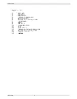
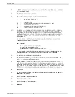
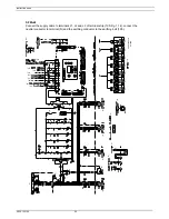
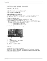
Connect the supply cable to terminals L1, L2 and L3 of terminal strip (1X0-Fig. 1.14), connect the 
neutral conductor to terminal (N) and the earthing conductor to the earthing bolt (1X3). 


O-

O-

O-

O-

O-

-

-

9820 3748 01/

2

     55105D

(1)

(2)

(3)

(4)

(5)

(6)

(7)

(8)

(9)

(10)

(11)

(12)

(13)

(14)

(15)

(16)

(17)

(5)

(18)

(19)

(20)

(21)

(22)

(23)

(24)

(25)

(26)

(27)

(28)

(3)

(3)

(3)


Содержание Air Compressor

Страница 1: ...e contents or any part thereof is prohibited This applies in particular to trademarks model denominations part numbers and drawings This instruction book meets the requirements for instructions specified by the machinery directive 98 37 EC and is valid for CE as well as non CE labelled machines No 2920 1521 00 Registration code APC SF 38 980 2003 10 www atlascopco com Note The PED instructions for...

Страница 2: ...hine is operated and that maintenance is carried out according to the instructions Record all operating data maintenance performed etc in an operator s logbook available from Atlas Copco Follow all relevant safety precautions including those mentioned on the cover of this book Repairs must be carried out by trained personnel from Atlas Copco who can be contacted for any further information In all ...

Страница 3: ... 3 2 1 Multi 28 3 2 2 Skid Tank mounted Twin 28 3 3 During operation 29 3 3 1 Multi 29 3 3 2 Skid Tank mounted Twin 29 3 4 Stopping 29 3 4 1 Multi 29 3 4 2 Skid Tank mounted Twin 29 3 5 Taking out of operation at end of compressor service life 29 4 MAINTENANCE 30 4 1 Compressor drive motors 30 4 2 Preventive maintenance schedule for the compressor 30 5 ADJUSTMENTS AND SERVICING PROCEDURES 32 5 1 A...

Страница 4: ...8 8 Modifying parameters 49 8 8 1 Modifying the pressure bands 50 8 9 Modifying protection settings 51 8 9 1 Checking protections for compressor modules 51 8 9 2 Modifying protections for Dryer LAT on Full Feature machines 52 8 10 Modifying service plans 52 8 11 Programming Clock function 54 8 11 1 Programming start stop pressure band commands 54 8 11 2 To activate deactivate the timer 56 8 11 3 T...

Страница 5: ...ncluding the start and stop buttons An emergency stop button is also provided An electric cabinet comprising the motor starter is installed behind the front door SF Multi Full Feature Figs 1 5 and 1 6 Full Feature compressors are Pack compressors additionally provided with an air dryer integrated in the bodywork The dryer removes moisture from compressed air by cooling the air to near freezing poi...

Страница 6: ...Instruction book 2920 1521 00 6 1 Control panel 2 Air outlet valve Fig 1 2 SF4 Skid 1 Control panel 2 Air outlet valve 1 3 SF4 Tank mounted ...

Страница 7: ...2920 1521 00 7 1 Control panels 2 Air outlet valve Fig 1 4 SF Twin 1 Elektronikon regulator 2 Electric cabinet 3 Air outlet valve 4 Dryer on Full Feature 5 Compressor modules S3 Emergency stop button Fig 1 5 SF8FF Multi ...

Страница 8: ...r outlet valve 4 Dryer on Full Feature 5 Compressor modules 6 Safety valve ASME S3 Emergency stop button Fig 1 6 SF15FF Multi 1 Air filter 2 Compressor element 3 Air cooler 4 Belts 5 Safety valve 6 Drive motor 7 Safety valve Fig 1 7 Details of a compressor module on SF Tank mounted ...

Страница 9: ...er towards the air net 1 3 Cooling and condensate drain systems Fig 1 9 Each compressor element is cooled by a fan The fan is mounted on the drive shaft of the compressor element The cooling air is blown over the compressor element and air cooler via a duct For SF Multi two fans driven by electric motors expel warm air from the bodywork SF Multi have a condensate trap with an automatic condensate ...

Страница 10: ... 4 Air pressure switch circuit breaker Fig 1 10 Control panel SF Skid Tank mounted Twin When the contacts are closed the circuit to the drive motor is made the compressor is operating The air output is maximum When the pressure reaches the pre set maximum the circuit to the drive motor is broken causing the compressor to stop The air output is stopped Protecting the compressor The compressor will ...

Страница 11: ... 1 5 2 Protecting the compressor If one or more compressor modules are shut down due to a protection function a warning message will be shown on the display The compressor will be shut down in case temperature switch TSHH20 Fig 2 8 trips See also section 8 3 2 Warning Before carrying out any inspection or repair stop the compressor switch off the voltage open the isolating switch and depressurize ...

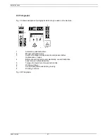
Страница 12: ...ble for modifying 5 Function keys Keys to control and program the compressor 6 Voltage on LED Indicates that the voltage is switched on 7 General alarm LED Is alight in case of a warning condition see section 8 3 7 General alarm LED Blinks in case of shut down condition if a sensor with shut down function is out of order or after an emergency stop See section 8 3 8 Automatic operation LED Indicate...

Страница 13: ... at the utmost right position of the display the key 3 with the same symbol can be used to see the previous item Tabulator key 4 Fig 1 11 This key labelled with two horizontal arrows allows the operator to go to the next field of the display e g during modifying of programmable parameters 1 5 7 Function keys 5 Fig 1 11 The keys are used To call up or program settings To reset an active shut down o...

Страница 14: ...mmable settings Program To program modified settings Reset To reset a timer or message Return To return to a previously shown option or menu Selecting a menu To facilitate controlling the compressor menu driven programs are implemented in the electronic module Use the function keys 5 to select the menus in order to program and monitor the compressor See also section 8 Fig 1 13 Menu flow SF Multi ...

Страница 15: ...ctric cabinet on SF Multi F1 8 Fuses K11 Auxiliary contactor dryer K21 24 Contactors Q21 24 Circuit breakers T1 2 Transformers 1X0 Terminal strip mains supply 1X2 Terminal strip dryer 1X3 6 Terminal strips Fig 1 14 Electric cabinets SF Multi ...

Страница 16: ...id flows through liquid refrigerant dryer filter 12 to capillary tube 7 The refrigerant leaves the capillary tube at evaporating pressure The refrigerant enters evaporator 11 where it withdraws heat from the compressed air by further evaporation at constant pressure The heated refrigerant leaves the evaporator and is sucked in by the compressor AO AI 5 6 4 3 2 1 13 11 12 REFRIGERANT LIQUID 3 REFRI...

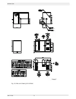
Страница 17: ...21 00 17 2 INSTALLATION 2 1 Dimension drawings Figs 2 1 up to 2 5 9820 4052 00 1 55100D 1 2 3 4 5 6 7 8 Fig 2 1 Dimension drawing SF 1 4 Skid 9820 4053 00 1 55101D 1 2 3 4 5 6 7 8 Fig 2 2 Dimension drawing SF 1 4 Tank mounted ...

Страница 18: ...54 00 1 55102D 1 2 2 1 3 4 5 6 7 8 Fig 2 3 Dimension drawing SF 6 8 Twin Text on Figs 2 1 2 3 1 Motor cooling air outlet 5 Electrical supply 2 Element cooling outlet 6 Type 3 Cooling air inlet 7 Pressure 4 Compressed air outlet 8 Mass approx ...

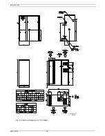
Страница 19: ...Instruction book 2920 1521 00 19 1 2 3 4 5 6 7 8 9 10 11 8 9 12 13 14 15 9820 4027 00 55098D Fig 2 4 Dimension drawing SF 6 8 Multi ...

Страница 20: ...Instruction book 2920 1521 00 20 9820 4026 00 55099D 1 16 2 3 4 5 6 7 8 9 10 11 8 9 12 13 14 15 Fig 2 5 Dimension drawing SF 11 15 Multi ...

Страница 21: ...essor cooling air outlet 5 Bodywork ventilation 6 Aftercooler and dryer cooling air outlet 7 Centre of gravity 8 With dryer 9 Without dryer 10 Dimensions 10 mm 11 Weight 12 Weight 10 kg 13 Compressor and bodywork cooling air inlet 14 Aftercooler and dryer cooling air inlet 15 Compressed air outlet 16 Data plate ...

Страница 22: ...struction book 2920 1521 00 22 2 2 Installation proposal Fig 2 6 9820 3960 00 55097D 3 1 2 Fig 2 6 Installation proposal SF Multi Text on Figs 2 6 1 Minimum free area 2 Compressor 3 Ventilation proposals ...

Страница 23: ...calculated as follows Qv 0 92 N dT Qv required ventilation capacity in m s N shaft input of compressor in kW dT temperature increase in compressor room in C For alternatives 2 and 4 the fan capacity should match the compressor fan capacity at a pressure head equal to the pressure drop caused by the outlet cooling air ducts 5 Position of control cubicle with monitoring panel 6 Position of main cabl...

Страница 24: ...h is open to isolate the compressor from the mains before carrying out any connection Connections Skid Tank mounted Twin Connect the cable to terminals 1 and 3 single phase or to terminals 1 3 and 5 3 phase of pressure switch 4 Fig 1 10 Connect the earthing conductor to the earthing terminal SF Twin have a pressure switch for each compressor module provide for each pressure switch separate supply ...

Страница 25: ... to terminals L1 L2 and L3 of terminal strip 1X0 Fig 1 14 connect the neutral conductor to terminal N and the earthing conductor to the earthing bolt 1X3 O O O O O 9820 3748 01 2 55105D 1 2 3 4 5 6 7 8 9 10 11 12 13 14 15 16 17 5 18 19 20 21 22 23 24 25 26 27 28 3 3 3 ...

Страница 26: ...minal strip dryer 1X3 6 Terminal strips Fig 2 8 Service diagram for SF Multi Text on Fig 2 8 1 Customer s installation 2 Door 3 Higher voltage Y Lower voltage D 4 Dryer 5 Optional 6 Supply of dryer 7 All other voltages 8 Marking of connectors 2X5 to 2X12 9 Pressure transducer pin configuration 10 Temperature sensor element 1 11 Temperature sensor element 2 12 Temperature sensor element 3 13 Temper...

Страница 27: ...in 2 Manual condensate drain 3 Switch off voltage and depressurize compressor before maintenance or repair 4 Before connecting compressor electrically consult Instruction book for motor rotation direction 5 Torques for steel Fe or brass CuZn bolts 6 Warning voltage 7 Consult Instruction book before greasing 8 Warning hot hose Fig 2 9 Pictographs ...

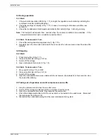
Страница 28: ...e air receiver if provided 5 Switch on the voltage Start and stop the compressor On 3 phase compressors check for correct direction of rotation arrows are provided on the motors If the rotation direction is wrong switch off the voltage and reverse two incoming electric lines 3 2 Starting 3 2 1 Multi 1 Open air outlet valve 3 Figs 1 5 1 6 2 Switch on the voltage 3 Close condensate drain valve 1 Fig...

Страница 29: ...econds close the valve after draining 3 4 Stopping 3 4 1 Multi 1 Press stop button 9 Fig 1 11 2 Close air outlet valve 3 Figs 1 5 1 6 3 Switch off the voltage 4 Open condensate drain valve 1 Fig 1 9 3 4 2 Skid Tank mounted Twin 1 Move switch 2 Fig 1 10 to OFF 2 Close air outlet valve 2 Figs 1 2 1 4 3 Switch off the voltage 4 Open the condensate drain valve underneath the air receiver if provided f...

Страница 30: ... Carry out the service operations at the period or running hours mentioned below whichever interval comes first When servicing replace all disengaged packings e g gaskets O rings washers Important Use only authorized parts Any damage or malfunction by the use of unauthorized parts is not covered by Warranty or Product Liability Service plans on SF Multi A number of service operations are grouped i...

Страница 31: ...densate trap internally Yearly 5 4 Test safety valve Have electrical components shut down switch tested 2500 I 5 2 Check tension condition of V belt s 5000 A 5 1 Replace air filter 5000 A 2 Have ball valve mechanism of condensate trap inspected 5000 A 5 2 Replace V belt s 2 yearly 5000 B 2 Have orbiting scroll bearing greased 10000 B 2 Clean compressor element fan and duct Clean compressor element...

Страница 32: ...Tension the belts by screwing bolts 4 equally The tension is correct if the deflection is between 5 mm and 7 mm when exerting a force of 25 N on the belt midway between the pulleys Make sure that the pulleys remain aligned The maximum out of line is maximum parallel out of line 0 5 mm maximum angular out of line 0 5 degrees 5 Tighten bolts 3 6 Check the belt tension after the first 500 running hou...

Страница 33: ...nscrewing the knurled cap one or two turns Retighten the cap Testing The valve can be tested on a separate compressed air line If the valve does not open at the pressure marked on the valve consult Atlas Copco Warning No adjustments are allowed Never run the compressor without safety valve ...

Страница 34: ...lve leaking c Replace valve d Drive belt s slipping d Check condition of belt s Correct or replace as required 4 Compressor module overheating compressor shut down by its air temperature switch a Insufficient compressor cooling a Improve ventilation of compressor room b Cooling fan out of order b Check and correct On SF Full Feature also 5 Pressure dewpoint too high a Shortage of refrigerant a Hav...

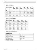
Страница 35: ... Hz 500 V 2 5 mm 2 5 mm 2x 2 5 mm 2x 2 5 mm CSA UL 60 Hz 200 230 V AWG 12 AWG 12 AWG 12 AWG 10 2x AWG 12 2x AWG 10 60 Hz 440 460 V AWG 12 AWG 12 2x AWG 12 2x AWG 12 7 2 Electric cable size for SF 6 15 Multi Frequency Voltage SF6 3 phase SF8 3 phase SF11 3 phase SF15 3 phase IEC 50 Hz 230 V 6 mm 10 mm 16 mm 25 mm 50 Hz 400 V 4 mm 6 mm 10 mm 10 mm 60 Hz 380 V 4 mm 6 mm 10 mm 10 mm 50 Hz 500 V 2 5 mm...

Страница 36: ...t value is valid for the smaller SF2 module and the second one is valid for the bigger SF4 module 7 4 Overload relays for SF6 15 Multi Frequency Voltage SF6 3 phase SF8 3 phase SF11 3 phase SF15 3 phase IEC 50 Hz 230 V 8 and 14 A 2x 14 A 3x 14 A 4x 14 A 50 Hz 400 V 4 8 and 8 A 2x 8 A 3x 8 A 4x 8 A 60 Hz 380 V 5 and 8 5 A 2x 8 5 A 3x 8 5 A 4x 8 5 A 50 Hz 500 V 3 6 and 6 4 A 2x 6 4 A 3x 6 4 A 4x 6 4...

Страница 37: ...n fuses for SF6 15 Multi Frequency Voltage SF6 3 phase SF8 3 phase SF11 3 phase SF15 3 phase IEC 50 Hz 230 V 32 A 50 A 63 A 80 A 50 Hz 400 V 25 A 32 A 50 A 50 A 60 Hz 380 V 25 A 32 A 50 A 50 A 50 Hz 500 V 20 A 25 A 32 A 50 A CSA UL 60 Hz 230 V 45 A 60 A 80 A 110 A 60 Hz 440 460 V 25 A 30 A 45 A 60 A 60 Hz 575 V 20 A 25 A 35 A 45 A 7 7 Reference conditions limitations Reference conditions Air inlet...

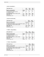
Страница 38: ... Skid approx C 45 65 Motor shaft speed r min 2885 2885 Shaft input kW 2 1 3 65 Sound pressure level dB A 67 68 7 10 SF1 4 100 psi 60 Hz 1 Compressor type SF1 SF2 SF4 100 psi 100 psi 100 psi Maximum working pressure bar e 8 8 8 Nominal working pressure bar e 7 7 7 Air temperature at outlet valve Tank mounted Twin approx C 30 32 40 Air temperature at outlet valve Skid approx C 38 45 65 Motor shaft s...

Страница 39: ...10 10 10 Nominal working pressure for SF Full Feature bar e 9 75 9 75 9 75 9 75 Air temperature at outlet valve for SF Pack approx C 26 28 30 32 Air temperature at outlet valve for SF Full Feature approx C 25 25 25 25 Motor shaft speed r min 2885 2885 2885 2885 Shaft input kW 5 9 7 5 11 3 15 0 Sound pressure level dB A 61 62 60 63 For SF Full Feature also Refrigerant type R134a R134a R134a R134a P...

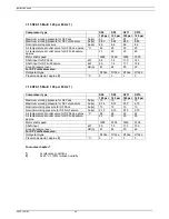
Страница 40: ...igerant type R134a R134a R134a R134a Pressure dewpoint approx 2 C 3 3 3 3 7 16 SF6 15 Multi 145 psi 60 Hz 1 Compressor type SF6 SF8 SF11 SF15 145 psi 145 psi 145 psi 145 psi Maximum working pressure for SF Pack bar e 10 10 10 10 Maximum working pressure for SF Full Feature bar e 9 75 9 75 9 75 9 75 Nominal working pressure for SF Pack bar e 10 10 10 10 Nominal working pressure for SF Full Feature ...

Страница 41: ...S FOR SF MULTI 8 1 Menu driven control programs To facilitate programming and controlling the compressor menu driven programs are implemented in the electronic module A simplified menu flow is shown in Fig 8 1 Fig 8 1 Menu flow SF15 Workplace Full Feature ...

Страница 42: ...fying the settings for parameters e g number of starts per day protections e g dewpoint temperature of dryer for Full Feature machines service plans see section 8 10 clock functions automatic compressor start stop pressure band commands configuration time date display language Service Calling up service plans and resetting the timers after carrying out the service actions belonging to a plan See s...

Страница 43: ...point sensor Stop the compressor Switch off the voltage and depressurize the compressor Check the sensor wiring Replace the sensor or transducer if necessary 3 Remote control Indicates that the compressor is set in remote control Consult Atlas Copco 4 Functions of keys below display See section 1 5 7 Symbols Indicating the status of each compressor module indicating that the compressor module is a...

Страница 44: ...pressor status display Line 1 indicates the automatic or manual operation status of the regulator Automatic operation means that the regulator automatically adapts the operation of the compressor i e starting and stopping the compressor modules according to the programmed parameters Line 2 indicates whether the regulator operates in local control remote control or LAN control mode Local control me...

Страница 45: ...ions are normal Fig 8 5 All Conditions are OK Menu Help F1 F2 F3 Fig 8 5 Example of a status data screen 8 3 2 A shut down message exists In case the compressor is shut down LED 7 will blink A shut down message exists after an emergency stop or after the temperature switch TSHH20 Fig 2 8 has tripped indicated on the display as Aux Equipment Overload In case of a shut down due to an emergency stop ...

Страница 46: ... F1 F2 F3 Fig 8 7 Example of a warning screen 2 The indicators are blinking and the message Warning appears alternately with the messages indicating whether the compressor is in operation or not Compressor Running or Compressor Off 3 Press the key Menu F1 and the tabulator key 5 to select the Status Data menu the option Protection is blinking 4 Scroll to this option and select it by pressing the t...

Страница 47: ...two options may blink Inputs option is not applicable Plan if a service plan interval is exceeded See section 8 15 2 5 Stop the compressor and switch off the voltage 6 The service message was referring to Plan carry out the service actions related to the indicated plans Reset the timers of the related plans as described in section 8 13 8 4 Measured data menu Function To call up information regardi...

Страница 48: ... see section 8 1 2 press the key Menu F1 press the key until the option Counters is followed by a horizontal arrow press the tabulator key 5 to activate the menu 2 By pressing the key the above mentioned data can be found see also Fig 8 1 8 6 Test menu Function To carry out a display test i e to check whether the display and LEDs are still intact Procedure 1 Starting from the Main screen see secti...

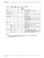
Страница 49: ...ver happens with the air net pressure Power recovery time if automatic restart after voltage failure is activated 3 Restart delay can be programmed allowing e g compressors to be restarted one after the other Time to next start time between the starting of two compressor modules Time to next stop time between the stopping of two compressor modules during regulation Procedure 1 Starting from the Ma...

Страница 50: ...d 1 High Pressure Band 1 High 7 8 bar Pressure Band 1 Low 6 8 bar Pressure Band 2 High 6 5 bar Menu Modify F1 F2 F3 Fig 8 11 Modify parameters menu 2 The screen shows that the current setting of Pressure Band 1 High is 7 8 bar e To modify this setting press the key Modify F2 Pressure Band 1 High 7 8 bar Program Limits Cancel F1 F2 F3 Fig 8 12 Modify parameters menu 3 The key Limits F2 can be used ...

Страница 51: ...ters is followed by a horizontal arrow press the tabulator key 5 to activate the menu 2 Use the key to scroll until the option Protections is followed by a horizontal arrow 3 Press the tabulator key 5 the first item Compressor outlet and its value will appear 4 Use the key to scroll until the parameter to be modified or checked is followed by a horizontal arrow 5 press the tabulator key 5 to selec...

Страница 52: ...5 Modify parameters menu 3 The key Limits F2 can be used to find the limitations for the parameter Use the or arrow key to change the value 4 Press the key Program F1 to program the new setting or the key Cancel F3 to cancel the modification operation Note The modifying procedure for other settings is similar For some settings a delay can be programmed See section 8 15 8 10 Modifying service plans...

Страница 53: ...cording to At Service plan I 2500 running hours Service plan I and A 5000 running hours Service plan I A and B 10000 running hours Service plan I A B and D 20000 running hours Procedure 1 Starting from the Main screen see section 8 1 2 press the key Menu F1 press the key until the option Modify parameters is followed by a horizontal arrow press the tabulator key 5 to activate the menu 2 Use the ke...

Страница 54: ...nd the other Service plans 8 11 Programming Clock function To program time based start stop commands for the compressor time based change over commands for the net pressure band see also section 8 8 1 8 11 1 Programming start stop pressure band commands In this example the compressor will be programmed as follows On Monday at 06 15 starting in pressure band 1 On Friday at 18 00 changing over to pr...

Страница 55: ...ress the tabulator key to jump to the row of dashes Use the or key to enter the command Start Press the key Program to program the command 06 15 Start 6 Press the key the symbol indicates that the second line is accessible Press the key Modify and modify this line to the following command line 06 15 Pressure Band 1 in a similar way 7 Press the key Back F1 and scroll to Friday Thursday Friday Satur...

Страница 56: ...he key Not activated changes into Activated 5 Press the key Program Important 1 It is necessary to program the start stop pressure band commands in successive order timewise e g 07 30 start 07 30 pressure band 1 08 30 pressure band 2 17 00 stop etc 2 Make sure that the clock function is activated indicated as Activated If not the programmed start stop commands will not be executed 8 11 3 To modify...

Страница 57: ...and start blinking Modify as required using the scroll keys i e in the example above change 18 into 17 using the key 5 If necessary press the tabulator key 5 to go to the next field to be modified the minutes indication and the start stop pressure band indication 6 Press the key Program to program the new command or the key Cancel to quit without reprogramming 8 11 4 To add a command Adding a comm...

Страница 58: ... the key Cancel to quit without reprogramming Adding a command between two existing commands 1 Suppose the command 17 00 pressure band 2 must be added to following list 06 00 start 06 00 pressure band 1 18 00 stop 2 The regulator does not allow to enter a new command which is situated timewise before the last command in the list 3 Scroll through the display until the command before which the new c...

Страница 59: ...til the desired start stop pressure band 1 or pressure band 2 command line is followed by symbol Press the key Delete F3 A question to confirm the deleting operation will appear 8 12 Configuration menu Function To reprogram a number of parameters See Fig 8 1 Procedure 1 Starting from the Main screen see section 8 1 2 press the key Menu F1 press the key until the option Modify parameters is followe...

Страница 60: ...opco Procedure 1 Starting from the Main screen see section 8 1 2 press the key Menu F1 press the key until the option Modify parameters is followed by a horizontal arrow press the tabulator key 5 to activate the menu 2 Use the key to scroll until the option Configuration is followed by a horizontal arrow 3 Press the tabulator key 5 The first option shown is C C M Compressor Control Mode followed b...

Страница 61: ...hours Service plan D Each 20000 running hours Resulting service actions to be carried out Service actions according to At Service plan I 2500 running hours Service plan I and A 5000 running hours Service plan I A and B 10000 running hours Service plan I A B and D 20000 running hours Procedure 1 Starting from the Main screen see section 8 1 2 press the key Menu F1 press the key until the option Ser...

Страница 62: ...screen shows that service plans A and I were carried out at 5008 running hours 5 Stop the compressor switch off the voltage and carry out the service operations related to plans A B and I 6 Switch on the voltage and scroll to the service screen shown in Fig 8 20 Press the Reset button F3 to reset the timer Confirm the question for resetting Notes The Reset button only appears when the next Timer l...

Страница 63: ... screen see section 8 1 2 press the key Menu F1 press the key until the option Saved data is followed by a horizontal arrow press the tabulator key 5 to activate the menu 2 The list of last shut down cases is shown 3 Scroll through the items to select the desired shut down item 4 Press the tabulator key 5 to find the date time and other data reflecting the status of the compressor at the last shut...

Страница 64: ... bar Full Feature bar e 4 8 8 9 7 100 psi Pack bar e 4 7 7 9 100 psi Full Feature bar e 4 6 8 7 7 125 psi Pack bar e 4 8 1 9 125 psi Full Feature bar e 4 7 75 8 8 145 psi Pack bar e 4 9 9 9 145 psi Full Feature bar e 4 8 8 9 7 Maximum pressure 2 8 bar Pack bar e 4 1 8 8 8 bar Full Feature bar e 4 1 7 8 7 8 10 bar Pack bar e 4 1 10 10 10 bar Full Feature bar e 4 1 9 8 9 8 100 psi Pack bar e 4 1 8 8...

Страница 65: ...hich the voltage must be restored to have an automatic restart can be set between 10 and 3600 seconds A delay at restarting can also be programmed allowing e g compressors to be restarted one after the other To activate the automatic restart function consult Atlas Copco 4 Full Feature version is the Pack version with integrated air dryer 5 Is the time period during which the warning signal must ex...

Страница 66: ...o not store the vessel near heating sources and inflammable substances and avoid storage of the vessel in badly ventilated rooms 7 Use vibration dampers to reduce the vibration during operation which can cause failure Do not mount the vessel to the ground or fixed structures 8 Drain condensate from the vessel daily to prevent corrosion inside the vessel During maintenance every 12 months check for...

Страница 67: ...Instruction book 2920 1521 00 67 Notes ...

Страница 68: ...Instruction book 2920 1521 00 68 Notes ...

Страница 69: ... h a l l n o t b e r e l i e d u p o n f o r i s o l a t i n g p r e s s u r e s y s t e m s 1 2 Neverremoveortamperwiththesafetydevices guardsorinsulations f i t t e do nt h eu n i t E v e r yp r e s s u r ev e s s e lo ra u x i l i a r yi n s t a l l e do u t s i d e t h e u n i t t o c o n t a i n a i r a b o v e a t m o s p h e r i c p r e s s u r e s h a l l b e p rot ec te d b y a p r e s s ...

Страница 70: ... t i v e l yi s o l a t et h e u n i t f r o m a l l s o u r c e s o f p r e s s u r e a n d r e l i e v e t h e e n t i r e s y s t e m o f p r e s s u r e 5 Never use flammable solvents or carbon tetrachloride for cleaning p a r t s Take safety precautions against toxic vapours of cleaning l i q u i d s 6 Scrupulously observe cleanliness during maintenance and repair Keep dirt away by covering t...

Отзывы: