ATI Technologies QC-313 Скачать руководство пользователя страница 9

Manual, Tool Changer, QC‑313
Document #9620‑20‑B‑313 Series Base Tool Changer‑06

Pinnacle Park • 1031 Goodworth Drive • Apex, NC 27539 • Tel: 919.772.0115 • Fax: 919.772.8259 • 

www.ati‑ia.com

 • Email: 

info@ati‑ia.com


B-9

2.4  Tool Interface

The Tool plate is attached to the customer’s tooling. An interface plate can adapt the Tool plate to customer 

tooling. Alignment features (dowel holes and a recess) accurately position and bolt holes to secure the Tool 
plate to customer tooling. Custom interface plates can be supplied by ATI (refer to the application drawing).
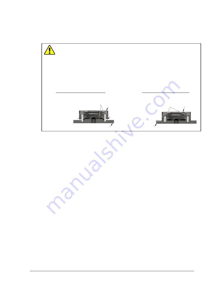
CAUTION:

 Do not use more than two alignment features when securing a Tool plate 

to an interface plate. Using more than two alignment features can cause damage to 
equipment. Use either two dowel pins or a single dowel pin, along with a boss/recess 
feature to align the Tool plate with the interface plate.

CAUTION:

 Do not use dowel pins that are too long or do not allow the interface plate 

and Tool body to mate flush. Using dowel pins that are too long will cause a gap 

between the interface plate and Tool body and damage the equipment. Use dowel pins 
that will not extend further than allowed by the Tool body.

Tool Plate

Interface Plate

Dowel pins are

proper size allowing

interface plate and Tool

Plate to mount flush.

Two dowel pins (or a

boss/recess) used as

alignment features.

Correct Mounting of Tool Plate

Tool Plate

Interface Plate

Dowel pins

are too long and

cause a gap between

interface plate and Tool.

Boss and two dowel pins

as alignment features can be

difficult to align and can

damage equipment.

Gap

Incorrect Mounting of Tool Plate

single dowel pin along with a

If the customer chooses to design and build a tool interface plate, consider the following points:

• 

The interface plate should include bolt holes for mounting and either two dowel pins or a dowel 
pin and a boss for accurate positioning on the customer tooling and Tool plate. The dowel and boss 
features prevent unwanted rotation.

• 

Dowel pins must not extend out from the surface of the interface plate farther than the depth of the 
dowel holes in the Tool plate.

• 

The thickness of the interface plate must be sufficient to provide the necessary thread engagement for 

the mounting bolts. Fasteners should meet minimum recommended engagement lengths while not 
exceeding the maximum available thread depth. Use of bolts that are too long can cause damage to the 
tool side changer.

• 

The plate design must account for clearances required for Tool Changer module attachments and 
accessories.

• 

If a boss is to be used on the interface plate, a boss of proper height and diameter must be machined 
into the interface plate to correspond with the recess in the Tool plate.

• 

The interface plate must have a hole in its center for manually returning the locking mechanism to the 
unlocked position under adverse conditions (i.e. unintended loss of power and/or air pressure). The 
center access hole with a minimum diameter of 1” (25.4 mm) prevents debris from contaminating the 
locking mechanism. Greater protection is provided by leaving the race cover and grommet in place.

Содержание QC-313

Страница 1: ...rements for Air Adapter Modules B 11 2 8 Electrical Connections B 12 2 8 1 PNP Type Lock Unlock and RTL Sensors SM sensor designations B 12 3 Operation B 13 3 1 Conditions for Coupling B 14 3 2 Fail S...

Страница 2: ...oodworth Drive Apex NC 27539 Tel 919 772 0115 Fax 919 772 8259 www ati ia com Email info ati ia com B 2 5 2 6 Alignment Pin Replacement B 31 6 Serviceable Parts B 33 6 1 Master Serviceable Parts B 33...

Страница 3: ...picks up the customer tooling a pneumatically driven locking mechanism couples the two plates The patented fail safe locking mechanism utilizes a multi tapered cam with ball locking technology to ens...

Страница 4: ...ng the coupling process An extreme pressure grease is applied to the cam male coupling ball bearings and pins to enhance performance and maximize the life of the Master plate assembly Proximity sensor...

Страница 5: ...late Assembly 2 Alignment Pin Bushing Bearing Race Proximity Sensor Assembly Target RTL Proximity Sensor Assembly Target RTL Common Ledge Feature for Module mounting 1 3 Optional Modules There are 6 f...

Страница 6: ...r applied to fasteners must not be used more than once Fasteners might become loose and cause equipment damage Always apply new thread locker when reusing fasteners CAUTION Do not use fasteners that e...

Страница 7: ...d Master plate to mount flush Two dowel pins or a single dowel pin along with a boss recess used as alignment features Flush Correct Mounting of Master Plate Master Plate Interface Plate Dowel pins th...

Страница 8: ...e is used fasteners to mount the Master plate is supplied with the interface plate 3 Connect utilities to the appropriate module and Master plate connections 4 If installation is complete the Master p...

Страница 9: ...erface plate and Tool Boss and two dowel pins as alignment features can be difficult to align and can damage equipment Gap Incorrect Mounting of Tool Plate single dowel pin along with a If the custome...

Страница 10: ...he Tool plate is supplied with the Interface Plate 3 Connect utilities to the appropriate module and Tool plate connections 4 If installation is complete the Tool plate may be put into normal operatio...

Страница 11: ...ve adapter module has an integrated solenoid valve and only requires the customer to supply a single air source to the valve adapter A customer supplied 2 position 4 way or 5 way valve with either 4 p...

Страница 12: ...d to seal the locking mechanism If a control signal module is to be utilized on Flat A when ordered the sensors will be connected to the module prior to shipping 2 8 1 PNP Type Lock Unlock and RTL Sen...

Страница 13: ...um complex grease with molybdenum disulfide For custom applications such as food grade or surgical applications specialized lubricants might be required Coupling should occur with the Master plate in...

Страница 14: ...lignment pins should be relatively concentric with the alignment bushings with no contact between the two 3 It is recommended that the mating faces of the Master and Tool not be touching but be within...

Страница 15: ...nintended loss of lock air pressure to the Master plate When air pressure is lost the Tool Changer relaxes and there may be a slight separation between the Master and Tool plates The lock sensor may i...

Страница 16: ...e solenoid valve turn the Unlatch output ON CAUTION This Tool Changer may be equipped with a tool stand Interlock TSI feature that physically breaks the Unlatch solenoid circuit Proper use of the TSI...

Страница 17: ...pecified Ideally the Tool should be hanging vertically in the tool stand so that gravity assists to uncouple the Tool plate from the Master plate during unlocking It is possible to design tool stands...

Страница 18: ...Application s Tool Change Frequency Inspection Schedule General Usage Material Handling Docking Station 1 per minute Weekly 1 per minute Monthly Welding Servo Deburring Foundry Operations Dirty Enviro...

Страница 19: ...1 Place the Tool in a secure location 2 Uncouple the Master and Tool plates 3 Turn off and de energize all energized circuits e g electrical air water etc 4 Use a clean rag to thoroughly remove any lu...

Страница 20: ...Apply a liberal coating of lubricant to the ball bearings the male coupling inside and out and the alignment pins Figure 4 4 Apply Lubricant to Locking Mechanism Apply Lubricant on Inner Surface of M...

Страница 21: ...ld Debris Blackened Pins 5 If debris or darkened pins are present use a vacuum to remove the debris and clean using a nylon brush ATI Part Number 3690 0000064 60 NOTICE Do not use an abrasive media cl...

Страница 22: ...er and Tool plates Clean debris from between Master and Tool plates Verify mounting fasteners is secure and does not protrude above the mating surfaces The ball bearings and or cam are not moving free...

Страница 23: ...M3 socket flat head cap screws and three cable retaining tabs on Flat D of the Tool Changer body 7 Unscrew the Lock and or Unlock sensor cable connector from the air valve adapter or control signal m...

Страница 24: ...3 M3 socket flat head cap screws using a 2 mm hex key Tighten to contact 15 If optional modules were installed on Flats D1 and D2 install modules 16 If fasteners do not have pre applied adhesive appl...

Страница 25: ...securing the sensor to the Tool Changer body 6 Unscrew the RTL sensor from the Tool Changer body 7 Discard the removed RTL sensor Figure 5 4 RTL Sensor Replacement RTL Sensor Jam Nut 8 Screw the new R...

Страница 26: ...nd three cable retaining tabs on Flat A of the Tool Changer body 7 Disconnect the sensor cable s from the sensor by pulling back on the locking sleeve Discard the cable Figure 5 6 RTL Sensor and Cable...

Страница 27: ...proximity to the face of the sensor and watching for the LED in the sensor cable to light up NOTICE Some control signal modules supply power to the RTL sensors in series The RTL R2 sensor will have to...

Страница 28: ...the 3 M3 socket flat head cap screws and three cable retaining tabs on Flat D of the Tool Changer body 8 Disconnect the sensor cable s from the sensor by pulling back on the locking sleeve Discard th...

Страница 29: ...e LED in the sensor cable to light up NOTICE Some control signal modules supply power to the RTL sensors in series The RTL R2 sensor will have to be switched before power is supplied to the RTL R1 sen...

Страница 30: ...in a secure location 2 Uncouple the Master and Tool plates 3 Turn off and de energize all energized circuits e g electrical air water etc 4 To remove the existing seal pinch the edge of the seal and...

Страница 31: ...ool in a secure location 2 Uncouple the Master and Tool plates 3 Turn off and de energize all energized circuits e g electrical air water etc 4 Unscrew the alignment pin assembly from the Master plate...

Страница 32: ...Key Master Plate Set Screw Alignment Pin Assembly 6 Once the alignment pin has been removed verify that the assembly pin and set screw are intact If the set screw portion of the assembly did not come...

Страница 33: ...nd PNP lock unlock and RTL sensing LED cables 9121 313DM 0 00 0 00 SM QC 313 Master with 125 mm Boss and PNP lock unlock and ready to lock sensors with LED cables 2 2 9005 20 1141 7 8 Two Piece Alignm...

Страница 34: ...www ati ia com Email info ati ia com B 34 6 2 Tool Serviceable Parts 1 2 3 Table 5 3 Standard Tool Plate Item No Qty Part Number Description 1 1 9121 313DT 0 0 0 0 QC 313 Tool with 125 mm Recess and...

Страница 35: ...ol Changer Maximum recommended working torque for optimum performance of the Tool Changer Positional Repeatability 0 0006 0 015 mm Repeatability tested at rated load at one million cycles Weight coupl...

Страница 36: ...From Far Side for M12 SHCS 30 Spacing Skip 12 Dowel Location Opposite Customer Interface Flat A Flat D2 Flat D1 Flat B1 Flat B2 Flat C Scale 1 4 Part Numbers A Master 9121 313AM 0 00 0 00 b Tool 9121...

Страница 37: ...ED See Sheet1 B 1 2 5 2 3 REVISION NOTES UNLESS OTHERWISE SPECIFIED DO NOT SCALE DRAWING ALL DIMENSIONS ARE IN MILLIMETERS DRAWN BY CHECKED BY M Perrault 8 1 12 ATM 8 1 12 TITLE SCALE SIZE DRAWING NUM...

Страница 38: ...1 2 5 3 3 REVISION NOTES UNLESS OTHERWISE SPECIFIED DO NOT SCALE DRAWING ALL DIMENSIONS ARE IN MILLIMETERS DRAWN BY CHECKED BY M Perrault 8 1 12 ATM 8 1 12 TITLE SCALE SIZE DRAWING NUMBER PROJECT SHEE...

Отзывы: