ATI Technologies 9105-NET-Axia80-M20-ZC22 Скачать руководство пользователя страница 1

Engineered Products for Robotic Productivity

Pinnacle Park • 1031 Goodworth Drive • Apex, NC 27539 • Tel: +1.919.772.0115 • Fax: +1.919.772.8259 • www.ati-ia.com

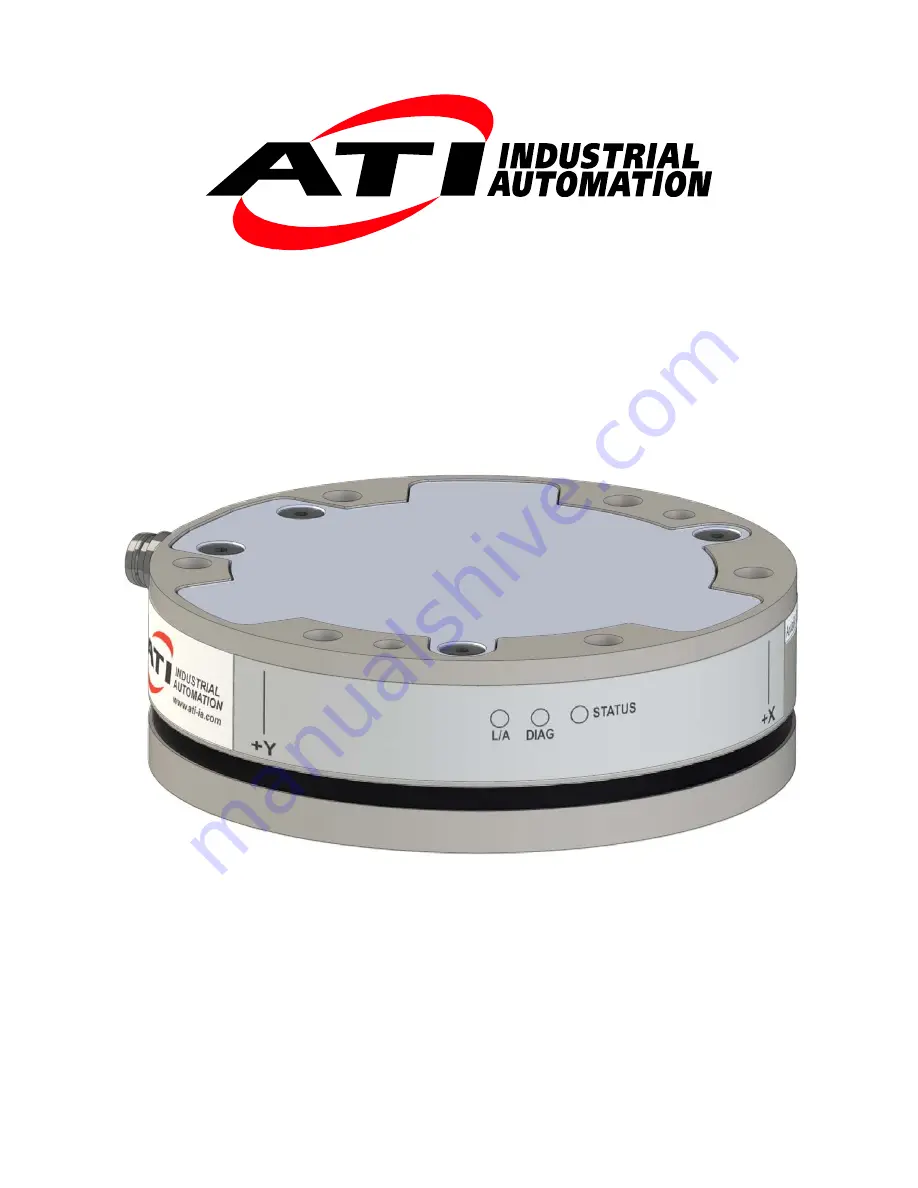
Ethernet Axia F/T Sensor 

Manual

Document #: 9610-05-Ethernet Axia

Содержание 9105-NET-Axia80-M20-ZC22

Страница 1: ...neered Products for Robotic Productivity Pinnacle Park 1031 Goodworth Drive Apex NC 27539 Tel 1 919 772 0115 Fax 1 919 772 8259 www ati ia com Ethernet Axia F T Sensor Manual Document 9610 05 Ethernet Axia ...

Страница 2: ...n that ATI Industrial Automation Inc ATI products are intended for use with robotic and or automated machines ATI does not recommend the use of its products for applications wherein failure or malfunction of a ATI component or system threatens life or makes injury probable Anyone who uses or incorporates ATI components within any potentially life threatening system must obtain ATI s prior consent ...

Страница 3: ...on of the question or problem For the status code refer to Section 4 8 Status Code 5 Computer and software information operating system PC type drivers application software and other relevant information about the configuration Be near the F T system when calling if possible Please contact an ATI representative for assistance if needed Sale Service and Information about ATI products ATI Industrial...

Страница 4: ...Manual F T Sensor Ethernet Axia Document 9610 05 Ethernet Axia 09 Pinnacle Park 1031 Goodworth Drive Apex NC 27539 Tel 1 919 772 0115 Fax 1 919 772 8259 www ati ia com 4 Statement of Compliance ...

Страница 5: ... 3 4 Removing the Sensor from the Robot 21 3 5 Pin Assignment for the Ethernet and Power Connection 22 3 5 1 Pin Assignment 6 pin Male M8 ZC22 Sensor Connector 22 3 5 2 Pin Assignment 8 Pin Male M12 ZC28 Connector 22 3 5 3 Pin Assignment for Cable P N 9105 C ZC28 U RJ45S X 23 3 5 3 1 Branch 1 Unterminated End for Power Connection 23 3 5 3 2 Branch 2 RJ45 Connection for Ethernet 23 3 6 Accuracy Che...

Страница 6: ... Using a Windows Computer 40 5 3 Finding the Ethernet Axia Sensor on a Network 43 6 Configuring the Sensor with the Ethernet Axia Web Pages 45 6 1 Welcome Page index htm 45 6 2 Snapshot Page rundata htm 46 6 3 Demo Page demo htm 47 6 4 ADC Settings Page setting htm 47 6 5 Thresholding Page moncon htm 48 6 6 F T Configurations Page config htm 51 6 7 Communication Page comm htm 52 6 8 System Informa...

Страница 7: ...ration Info Response 76 10 6 Write Tool Transform Command 77 10 7 Write Monitor Condition Command 77 10 8 Write Response 77 11 System Settings XML Pages 78 11 1 System and Configuration Information netftapi2 xml 78 11 2 Calibration Information netftcalapi xml 80 12 UDP Interface Using RDT 81 12 1 RDT Protocol 81 12 1 1 RDT Request For Records Structure 82 12 1 2 RDT Records Sent Structure 82 12 2 ...

Страница 8: ...ernet and Host 88 14 8 2 Choice of Operating System 88 14 8 3 Increasing Operating System Performance 88 14 8 4 Avoid Logging the Host to a Company Network 89 14 8 5 Use a Dedicated Network 89 15 Specifications 89 15 1 Environmental Conditions 89 15 2 Electrical Specifications 89 15 3 Calibration Ranges 89 16 Drawings 90 16 1 Axia80 Force Torque Sensor 9230 05 1543 90 16 2 Cable Axia Sensor to 8 p...

Страница 9: ...orce and Torque Fxy The resultant force vector comprised of components Fx and Fy HEXn Hexadecimal number of n bits prefixed with 0x HTTP GET Method A standard and common method that a user can request data from a specified resource such as a sensor HTTP works as a request response protocol between client web browser and server the sensor Hysteresis A source of measurement error caused by the resid...

Страница 10: ...a UDP RDT Buffer Size A mode where the sensor sends more than one data package per sample Multiple data packages are buffered and sent in one block Buffering reduces the amount of overhead data sent from the sensor and reduces the overall network traffic Resolution The smallest change in load that can be measured Sample Rate How fast the ADCs are sampling inside the unit Sense loads The ATI F T se...

Страница 11: ...ication provides information about the nature of the hazardous situation the consequences of not avoiding the hazard and the method for avoiding the situation WARNING Notification of information or instructions that if not followed could result in death or serious injury The notification provides information about the nature of the hazardous situation the consequences of not avoiding the hazard an...

Страница 12: ...Safety Precautions CAUTION Modifying or disassembling the sensor could cause damage and void the warranty CAUTION Probing openings in the sensor causes damage to the instrumentation Avoid prying into the openings of the sensor CAUTION Do not overload the sensor Exceeding the single axis overload values of the sensor causes irreparable damage CAUTION Do not contact the IP64 seal Contacting the seal...

Страница 13: ...r more information The sensor is IP64 rated An M8 6 pin male connector is for power and Ethernet For the pin assignments refer to Section 3 5 Pin Assignment for the Ethernet and Power Connection for Ethernet and power The Ethernet Axia sensor offers the following features Calibrated force torque data Bias functionality Programmable low pass filtering with cut off frequency Tool transformation Thre...

Страница 14: ...Part Number Number of Identifying Grooves1 Material Axia80 M8 9105 NET Axia80 M8 ZC22 3 Aluminum Axia80 M20 9105 NET Axia80 M20 ZC222 0 Axia80 M50 9105 NET Axia80 M50 ZC22 2 Stainless Steel Notes 1 Identifying grooves are physical indentations in the sensor body refer to Figure 2 2 These grooves provide users a quick visual method to differentiate the sensor models 2 Formally 9105 NET Axia80 ZC22 ...

Страница 15: ...the sensor Failure to follow proper grounding procedures could damage the sensor CAUTION Do not apply excessive force to the sensor and cable connector during installation or damage will occur to the connectors Align the keyway on the sensor and cable connector during installation to avoid applying excessive force to the connectors Keyway on the cable connector Keyway on the sensor connector 3 1 I...

Страница 16: ...ins that exceed length requirements and prevent the interface plate from mating flush with the robot and customer tooling Fasteners that exceed length requirements create a gap between the interfacing surfaces and cause damage The interface plate must not distort from the maximum force and torque values that can be applied to the sensor For these values refer to Section 15 Specifications The inter...

Страница 17: ...applications where the cable is in a static condition dynamic applications subject the cable to a repetitive motion For dynamic applications restrain the cable at a distance that does not expose and damage the sensor s cable connection from the robot s repetitive motion NOTICE The maximum supported cable length is 25 m Figure 3 2 Routing of the Sensor Cable Mounting Interface Plate Sensor Cable F ...

Страница 18: ...he zip tie does not contact the cable CAUTION Improper cable routing may cause injury to personnel poor functionality of critical electrical lines or damage to the equipment The electrical line especially where attached to the senor s connector must be routed to avoid stress failure sharp bends or a disconnection from the equipment Damage to the sensor or cable from improper routing will void the ...

Страница 19: ...ightening the straps on the cable CAUTION When routing the cables do not bend less than the minimum bending radius specified in Table 3 1 A bend radius too small causes the cable to fail from fatigue of the robot s repetitive motion Table 3 1 Sensor Cable Bending Radius and Dynamic Twist Angle Cable Part Number Spliced Cable Branch Description Cable Diameter mm in Static Bending Radius at room tem...

Страница 20: ... class 12 9 so that the fasteners secure the sensor to the mounting plate 3 Attach the sensor to the mounting interface plate a Using a 4 mm hex key secure the sensor to the mounting interface plate with 6 M5 socket head cap screws class 12 9 Tighten the fasteners per the specifications in the following table Table 3 2 Torque Values for Axia Models Model Torque Axia80 M8 52 in lbs 5 88 Nm Axia80 M...

Страница 21: ... 9105 C ZC22 ZC28 4 Ethernet Axia Sensor Power and Ethernet Cable to the customer s application ATI P N 9105 C ZC28 U RJ45S 4 Unterminated End for Power Branch 1 RJ45 Connector Branch 2 Power and Ethernet Connection Tool Side for the Customer Tooling Mounting Side to the Interface Plate 3 4 Removing the Sensor from the Robot Tools required 4 mm hex key 1 Turn off all energized circuits for example...

Страница 22: ...protected If the power and ground to the power supply inputs are plugged in reverse then the reverse polarity protection stops the incorrectly wired supply input from damaging or powering on the sensor 3 5 1 Pin Assignment 6 pin Male M8 ZC22 Sensor Connector Signals and corresponding pin numbers for the 6 pin male M8 ZC22 sensor connector are in the following table Table 3 4 Pin Assignment for the...

Страница 23: ...or the unterminated wires which connect to the customer s device are in the following table Table 3 6 Branch 1 Unterminated End Wire Jacket Color and Signal Wire Jacket Color Signal Shield Brown V Brown White V Blue White TP1 1 Sync Blue TP1 1 Sync Ground Note 1 Reserved not used 3 5 3 2 Branch 2 RJ45 Connection for Ethernet The signals and corresponding pin numbers for the 8 pin RJ45 connect whic...

Страница 24: ... fixed mass to the tool side of the F T sensor a Remove cables that form bridges between the sensor s mounting and tool sides 2 Power on the sensor Allow a 30 minute warm up time Minimize external sources of temperature change 3 Move the robot so that the sensor is in the following positions a Record the sensor s output Fx point n Fy point n Fz point n at each point without biasing Point 1 Z up Po...

Страница 25: ...ensor s rated accuracy is 2 the range on all axes For a 500 N Fxy range and a 900 N Fz range the allowable errors of any single data point would be 10 N Fx y and 18 N Fz respectively Since Fz has the larger tolerance then one data point could be 18 N and another data point could be 18 N for a total range max min of 36 N error In addition the tooling mass should be within 36 N of the results of thi...

Страница 26: ...rated to prevent sensor damage NOTICE Sensors may react to exceptionally strong and changing electromagnetic fields such as those fields created by magnetic resonance imaging MRI machines The user must ensure that the dust and water in the environment does not exceed the IP64 rating of the sensor 4 2 LED Outputs The Ethernet Axia sensor provides 3 LED units for Link Activity L A Diagnostic DIAG an...

Страница 27: ...z 976 Hz 1953 Hz 3906 Hz 7912 Hz 4 3 1 Sample Rate Versus Data Rate The data rate is how fast data can be output over the Ethernet network If the data rate is faster than the sample rate the customer sees duplicate samples output over the network until the next sample is read internally A faster data rate could be useful so that the sensor sends data at the same rate that other devices in a custom...

Страница 28: ...e cutoff frequencies for the different sampling rates are listed in the following table Table 4 6 Low Pass Filtering Selected Filter 3dB Cutoff Frequency in Hz at 488 Hz Sample Rate at 976 Hz Sample Rate at 1953 Hz Sample Rate at 3906 kHz Sample Rate at 7912 Hz Sample Rate 0 200 350 500 1000 2000 1 58 115 235 460 935 10 2 22 45 90 180 364 04 3 10 21 43 84 169 52 4 5 10 20 40 81 24 5 2 5 5 10 20 39...

Страница 29: ...ttenuation at 1 kHz Sample Rate 30 0 dB 24 0 dB 18 0 dB 12 0 dB 6 0 dB 0 0 dB 0 Hz 1 Hz 10 Hz 100 Hz 1000 Hz 115 Hz 350Hz 45 Hz 21 Hz 10 Hz 5 Hz 3 Hz 1 2 Hz Frequency Attenuation 0 7 Hz Figure 4 3 Filter Attenuation at 2 kHz Sample Rate 30 0 dB 24 0 dB 18 0 dB 12 0 dB 6 0 dB 0 0 dB 0 Hz 1 Hz 10 Hz 100 Hz 1000 Hz 500 Hz 235 Hz 90 Hz 43 Hz 20 Hz 10 Hz 2 4 Hz 5 Hz 1 4 Hz Frequency Attenuation ...

Страница 30: ... Rate 30 0 dB 24 0 dB 18 0 dB 12 0 dB 6 0 dB 0 0 dB 0 Hz 1 Hz 10 Hz 100 Hz 1000 Hz 2 7 Hz 4 7 Hz 10 Hz 20 Hz 40 Hz 84 Hz 180 Hz 460 Hz 1000 Hz Frequency Attenuation Figure 4 5 Filter Attenuation at 8 kHz Sample Rate 30 0 dB 24 0 dB 18 0 dB 12 0 dB 6 0 dB 0 0 dB 0 Hz 1 Hz 10 Hz 100 Hz 1000 Hz 10000 Hz 373 Hz 958 Hz 2000 Hz 935 10 Hz 364 04 Hz 169 52 Hz 81 24 Hz 39 84 Hz 20 31 Hz 9 37 Hz 5 47 Hz Fre...

Страница 31: ...ensor As a result the sensor could be overloaded refer to Section 4 7 1 Avoid Overloading the Sensor During Tool Transformation Therefore when evaluating overloading conditions use the sensor s point of origin as the reference point The user defines a reference point by inputting a parameter set that is a series of 3 displacements Dx Dy Dz and 3 rotations Rx Ry Rz for example Dx 97 3 mm Dy 46 1 mm...

Страница 32: ...rotation Y Axis after X rotation Z Z Axis after X rotation 2 The second rotation is about the Y axis of the new user output reference frame In this example Ry 180 rotation The user point of origin rotates 180 about the Y axis of the new user output reference frame in the following figure Figure 4 8 Tool Transformation Rotation About the Y Axis The robot side of the sensor The tool side of the sens...

Страница 33: ...ny force that is multiplied by a distance of zero yields zero torque The software tool transformation reports that no torque is applied to the sensor However the sensor s point of origin has not changed and the force is still applied at a distance from the sensor s point of origin Therefore if the customer is evaluating overloading conditions the customer should use the sensor s point of origin as...

Страница 34: ... A user wants to set the point of reference from the example in Figure 4 6 through Figure 4 8 Dx 97 3 mm Dy 46 1 mm Dz 201 82 mm Rx 90 rotation Ry 180 rotation Rz 0 rotation Open a web browser and enter a URL request http 192 168 1 1 config cgi cfgtdu 3 cfgtau 1 cfgtfx0 97 3 cftgtfx1 46 1 cfgt fx2 201 82 cfgtfx3 90 cfgtfx4 180 cfgtfx5 0 This request tells the sensor at IP address 192 168 1 1 to se...

Страница 35: ...g the calibration in use Changing the ADC sampling rate Any ADC ISR overrun No 4 Reserved Yes 5 Common error bit Yes 6 to 15 Reserved Yes 16 Monitor Condition 0 15 Latched No 17 to 26 Reserved Yes 27 Gage Out of Range The bit is set whenever a gage sample is outside of the range gageMinRange to gageMaxRange This bit stays high for 32 samples after the last such sample so that time abates for the s...

Страница 36: ...d ranges that are used in the preceding equations For example An Axia80 M20 sensor that uses calibration range 0 SI 500 20 is subjected to the following loads and has the following calibration ranges Table 4 8 Example of Force Torque Out of Range Axis Applied Load Calibration Range 0 Table 15 3 Value Fx 87 5 N 500 N Fy 151 6 N 500 N Fz 500 0 N 900 N Tx 1 0 Nm 20 Nm Ty 2 0 Nm 20 Nm Tz 17 5 Nm 20 Nm...

Страница 37: ...28 Simulated error 0x10000000 29 Calibration checksum error 0xA0000000 30 F T out of range 0xC0000000 31 Any error 0x80000000 Healthy 0x00000000 The bit pattern can be different if more than one error is present For example a user issues this console command refer to Section 8 3 Secondary Commands for the Query c or s Command user s response 80000005 Using a free online calculator convert the hexa...

Страница 38: ...t of range Common error Simulated error Monitor condition latched Error unspecified Good no status code errors System health indicators that the Axia F T firmware monitors are in the following table Table 4 11 Network Health System Indicator Description Stack Usage The maximum amount of the stack usage is continuously monitored An error message is generated if the available stack is too low MCU Pr...

Страница 39: ...d contact their IT department for assistance The 9105 C ZC28 U RJ45S X cable has a RJ45 adapter that is compatible with standard office grade Ethernet cables CATS or higher that have RJ45 connectors 5 1 IP Address Configuration for Ethernet To apply new IP address settings power cycle the sensor New IP address settings are only loaded upon power up Configure an IP address for the Ethernet Axia sen...

Страница 40: ...Open the computer s Internet Protocol TCP IP Properties window For Windows 7 8 10 operating system complete the following steps a From the Start menu select the Control Panel b Click on the Network and Internet icon c Click on the Network and Sharing Center icon d Click on the View network status and tasks link e Click on the Local Area Connection link f A new window opens that displays the genera...

Страница 41: ...sses must be unique to each device If 192 168 1 100 is already used by any other devices on the network use another IP address with the same first three fields as the sensor 5 In the IP address field type 192 168 1 100 6 In the Subnet mask field type 255 255 255 0 7 Click on the OK button 8 On the Local Area Connection Properties window click the Close button 9 Use an Ethernet cable to connect the...

Страница 42: ...a Sensor on a Network NOTICE When assigned by a DHCP server IP addresses are not permanent and may change if the Ethernet Axia Sensor is disconnected from the network for a period of time Users should contact their IT department in this situation Static IP addresses are more favorable in permanent Ethernet F T applications because the IP address does not change For a complete description of the fi...

Страница 43: ...Demo from the ATI website https www ati ia com Products ft software net_ft_software aspx 2 The first time this discovery tool is downloaded the program may trigger a firewall alert Select the check boxes to give permission for the network to communicate with the sensor and click the Allow access button Figure 5 4 Windows 7 8 10 Firewall Alert NOTICE If the network is still not able to communicate ...

Страница 44: ...919 772 8259 www ati ia com 44 Figure 5 5 Discovery Tool NOTICE In addition to the ATI website ATI provides this discovery tool in a directory that is sent to the user upon receipt of the sensor To access the tool in the directory 9030 05 1026 open the folder Utilities open the folder ATI Discovery Tool and then install the file named setup ...

Страница 45: ...ble The demo program is written in Java and requires Java to be installed on the computer The system status is displayed on all pages near the top of the page This is the system status at the time the user loaded the page To display the current system status the user must reload the page Possible system status conditions are listed in Section 4 8 Status Code Screenshots and a summary of the page s...

Страница 46: ... force and torque data scaled with the counts per force and counts per torque displayed on the Configurations page For more information about how F T values are scaled refer to Section 4 4 Converting Counts Per Force Torque to F T Values If any strain gages are overloaded these values are invalid and displayed in red with a line through them Strain Gage Data Unbiased Gage Data These fields display...

Страница 47: ...load the Java Demo Application Refer to Section 7 Java Demo Application for more information Figure 6 4 Demo Page 6 4 ADC Settings Page setting htm On the ADC Settings page the user can select the following the active calibration ADC sampling frequency low pass filter cutoff frequency and software bias values When the user clicks the Apply button the changes on this page are implemented on the sen...

Страница 48: ...set applied to the sensor strain gage readings To remove the bias offset set the fields to all zeros Note that the strain gage readings do not have a 1 1 correspondence to force and torque readings 6 5 Thresholding Page moncon htm On the Thresholding page the user can set up to 16 threshold conditions Threshold conditions compare the sensor readings to simple user defined threshold statements Afte...

Страница 49: ...ny condition is true or bitwise AND ing trigger only if ALL conditions are true Reset Latch button Clears any threshold latching Relay Momentary The user may select in how many tenths of a second 0 to 25 5 seconds that the Minimum On Time the firmware should wait in momentary mode before automatically resetting the monitor latch condition In case of any enabled threshold condition becoming true th...

Страница 50: ...iption Greater Than Less Than Counts The loading level to be compared to the sensor reading This value displays in the units of the active configuration after the user clicks the Apply button To determine the Counts value to use from a value in user units multiply the value in user units by Counts per Force or Counts per Torque if appropriate Example Desired Loading Level 6 25 N Force Units N from...

Страница 51: ...atuses button to update the static display of the threshold status If a threshold is unsatisfied the threshold numbers are crossed out 6 6 F T Configurations Page config htm On the Configurations page a user may select the active calibration Section 15 3 Calibration Ranges and tool transformation settings for the sensor system When the user clicks the Apply button the changes on this page are impl...

Страница 52: ...PAddress The user can set the static IP address refer to Section 5 1 IP Address Configuration for Ethernet Static IP Subnet Mask This field is for the subnet mask portion of the IP address Many networks use the default 255 255 255 0 Users should contact their IT department to know what static IP subnet mask to assign IP Default This field is for the default gateway Users should contact their IT de...

Страница 53: ...e ATI refers to this page when troubleshooting the sensor For status codes refer to Section 4 8 Status Code On the top of the page System Status is good if all hardware diagnostics report good The System Status is bad if any hardware diagnostics report bad Figure 6 9 System Information Page 6 9 ATI Web Site Menu item On the menu bar if the user clicks the ATI Web Site button the user goes to ATI I...

Страница 54: ...ctions The file ATINetFT jar downloads If the browser does not automatically run the downloaded file manually open the file on the computer Figure 7 1 Demo Page NOTICE The Java Demo requires the Ethernet F T to have its RDT Interface enabled RDT is enabled in the Ethernet F T by default For information on RDT settings refer to Section 6 7 Communication Page comm htm The demo program opens with the...

Страница 55: ...tion mark Figure 7 3 Java Demo Application The first time the demo is used the program may trigger a firewall alert If this occurs with a Windows 7 8 10 operating system select the check boxes to give permission for the network to communicate with the sensor and click the Allow access button refer to Figure 7 4 If this occurs with a Windows Vista operating system click the Unblock button refer to ...

Страница 56: ...ing Data with the Demo To collect F T data follow these steps 1 On the Java demo application main window select a file to save the data by one of the following methods refer to Figure 7 6 click the button to the right of the file selection field and navigate to the file destination directly type the file path into the file selection field 2 Click the Start Collecting button refer to Figure 7 3 The...

Страница 57: ... 1031 Goodworth Drive Apex NC 27539 Tel 1 919 772 0115 Fax 1 919 772 8259 www ati ia com 57 Figure 7 6 Java Demo Application while Collecting Data 5 To stop collecting data click the Stop Collecting button the Collect Streaming button changes to Stop Collecting during collections ...

Страница 58: ...cation Page comm htm Note If the user changes the sample rate after start of the demo program this value will not be updated Row 3 Force Units the force unit the user select on the Configuration page refer to Section 6 6 F T Configurations Page config htm Row 4 Counts per Unit Force Divide all force values Fx Fy Fz in the CSV file by this number to calculate the force values in the user selected u...

Страница 59: ... the following formula Rate Sample RDT Number Sequence RDT Time t Measuremen Elapsed Missing sequences indicate that data packages were lost To avoid lost samples refer to Section 14 8 Improving Ethernet Throughput Column C F T Sequence a number that is incremented with each new F T measurement The user sets the rate on the ADC settings page Refer to Section 6 4 ADC Settings Page setting htm Colum...

Страница 60: ...tance with troubleshooting these error messages refer to Table 14 3 If there are excessive IO Exception Receive timed out errors refer to Section 14 8 Improving Ethernet Throughput Figure 7 8 Java Demo Application with an Error Message 7 6 Developing a Customized Java Application Experienced Java programmers can develop Ethernet F T applications by using Java source code that is in the 9030 05 102...

Страница 61: ...computer the user can communicate with the sensor Free Telnet console software such as PuTTY is available online For instructions on setting up a console through Telnet like PuTTY refer to the following procedure 1 Open the serial console for example PuTTY A window opens that allows the user to set the configuration for the session 2 Set the configuration a Under Connection type select the radio b...

Страница 62: ...Commands which are entered are not case sensitive Figure 8 2 PuTTY Terminal Window 8 2 Console Commands These console commands can be used to view the status parameters and adjust settings of the sensor Table 8 1 Commands Command Operand s Description HELP The help command reports a list of the console commands and software version H MAN BIAS The bias command allows the user to turn the bias featu...

Страница 63: ...e CAL or SET command reports all parameters field name Print all matching field s refer to Section 8 4 Console CAL SET Command Fields and Values field name value Write field with value refer to Section 8 4 Console CAL SET Command Fields and Values SIMERR The simulated error command refers to bit 28 from Table 4 7 A user can issue this command to view the status of bit 28 The simulated error comman...

Страница 64: ... following gage number gage readings in counts gage status indicator F T axis F T reading in units all time peak data and the active tool transformation 8 3 Secondary Commands for the Query c or s Command A user can adjust the type of data reported from the query c or s by using secondary commands or specifiers This feature is useful for users who want to develop their own program for storing the ...

Страница 65: ...umeric System h The data is displayed as a hexadecimal number Except any data printed in units is always displayed as a decimal number by default d The data is displayed as a decimal number Format The data is displayed in a formatted human readable output for example lined up columns is the default setting The data is displayed in a compressed output that has no leading zeros trailing zeros or unn...

Страница 66: ... 965 a The S is a command for reporting a single line of data b The C and D specifies printing x y z or m F T data in counts decimal c The F specifies printing torques whenever an X Y Z or M is seen from now on on this line d The T specifies printing the torques whenever an X Y Z or M is seen from now on on this line 8 4 Console CAL SET Command Fields and Values A user can send the CAL or SET comm...

Страница 67: ...e units 0 Lbf in 1 Lbf ft 2 Nm 3 Nmm 4 Kg cm 5 kN m 2 cpf Counts per Force Calibration counts per force unit 1000000 32 bit unsigned integer Read cpt Counts per Torque Calibration counts per torque unit peakPos0 PeakLoadsPosFx All time peak positive force torque loads that are in F T counts 2395927 32 bit unsigned integer Read peakPos1 PeakLoadsPosFy 624574 peakPos2 PeakLoadsPosFz 0 peakPos3 PeakL...

Страница 68: ...DT transmission rate must be 1 to the adcRate 40 16 bit integer Read and Write rdtSize The number of RDT records to include in each UDP packet that is transmitted filTc N A The IIR filter shift value refer to Table 4 6 0 8 bit integer Read and Write calib N A The calibration to use 0 or 1 This bit controls which of the two sets of calibrations are displayed in the preceding fields refer to Table 1...

Страница 69: ...ol transformation angle units 0 degrees 1 radians ttdx Dx Tool transform distances refer to Section 4 7 Tool Transformation 0 float ttdy Dy ttdz Dz ttrx Rx Tool transform rotation angles refer to Section 4 7 Tool Transformation ttry Ry ttrz Rz tt N A Perform tool transformation N A baud N A UART baud rate Must be in range from 300 baud to 3M baud Any baud rate change is temporary until a SAVEALL c...

Страница 70: ...nteger Read and Write mcOutMomen Global monitor conditions are momentary or latching When latching is set processing of monitor conditions is suspended and monitor condition data is inactive 0 latching 1 momentary reset 1 mcOutDelay N A A delay the firmware should wait in momentary mode before automatically resetting the monitor condition latch The user can type a value between 0 and 225 This valu...

Страница 71: ...est netFTAddress is the Ethernet address of the Ethernet Axia sensor a separator CGIPage cgi the name of the CGI page that holds the variables you will be accessing a separator marking the start of variable assignments firstVariableAssignment a variable assignment using the format described below nextVariableAssignment a variable assignment using the following format but the variable name is proce...

Страница 72: ... Cutoff 0 no filter 5 0 51 1 11 97 6 0 26 2 4 66 7 0 12 3 2 17 8 0 07 4 1 04 setbiasn integers 32768 to 32767 Sets the offset value for strain gage n For example setbias3 0 would zero the bias of the fourth strain gage Strain gages are enumerated starting at zero setbias3 0 9 3 Thresholding CGI moncon cgi A user can define Thresholding settings and conditions Table 9 2 moncon cgi Threshold Setting...

Страница 73: ...hold statement n mco0 0x00 Note 1 where n is an integer ranging from 0 to 15 representing the threshold statement index 9 4 CGI Variable Configurations config cgi The user can set the calibration and tool transformation for the sensor refer to Section 6 6 F T Configurations Page config htm for related information An example of setting tool transformation parameters is in Section 4 7 3 Example of T...

Страница 74: ...rotation Ry with the units that are specified in the variable cfgtau cfgtfx5 Sets the tool transformation rotation Rz with the units that are specified in the variable cfgtau 9 5 CGI Variable Communications comm cgi A user can set the networking options of the sensor refer to Section 6 7 Communication Page comm htm for more information Table 9 5 comm cgi Variables Variable Name Allowed Values Desc...

Страница 75: ...ds Bitmap of system commands Each bit position 0 15 in MCEnable corresponds to the monitor condition at that index If the bit is a 1 that monitor condition is enabled If the bit is a 0 that monitor condition is disabled Bit 0 of sysCommands controls the Bias If bit 0 is a 1 the system is biased If bit 0 is a 0 no action is taken Bit 1 of sysCommands controls the monitor condition latch If bit 1 is...

Страница 76: ...e unit uint32 countsPerTorque Calibration Counts per torque unit uint16 scaleFactors 6 Further scaling for 16 bit counts The status code is the upper 16 bits of the 32 bit status code described in the Net F T user manual The force and torque values in the response are equal to actual ft value calibration counts per unit 16 bit scaling factor The counts per unit and scaling factor are read using th...

Страница 77: ...nteger numbers The distance unit codes are 1 Inch 2 Foot 3 Millimeter 4 Centimeter 5 Meter The angle unit codes are 1 Degrees 2 Radians The response is a standard Write Response 10 7 Write Monitor Condition Command uint8 command Must be WRITETHRESHOLD uint8 index Index of monitor condition 0 31 uint8 axis 0 fx 1 fy 2 fz 3 tx 4 ty 5 tz uint8 outputCode Output code of monitor condition int8 comparis...

Страница 78: ... Unsigned short integer 8 bit The values of all data types are presented as an ASCII strings Arrays are represented if the suffix i is attached to the data type where i indicates the number of values in the array Array values in an XML element may be separated by a semicolon comma or space 11 1 System and Configuration Information netftapi2 xml The XML page netftapi2 xml retrieves the system setup...

Страница 79: ... active configuration cfgtdu USINT Tool transformation distance units that are used by an active configuration scfgtdu STRING16 Name of tool transformation distance units that are used by an active configuration cfgtau USINT Tool transformation rotation units that are used by an active configuration scfgtau STRING8 Name of tool tranformation rotation units that are used by an active configuration ...

Страница 80: ...ation index is not specified the currently used calibration will be assumed For example to retrieve calibration information for the second calibration the requested page would be netftcalapi xml index 1 Table 11 3 XML Elements in netftcalapi xml XML Element Data Type Calibration Information calsn STRING8 Serial number calpn STRING32 Calibration type caldt STRING20 Calibration date calmtx REAL Matr...

Страница 81: ...UDP port is 49152 In the RDT protocol there are 4 commands that are listed in following table A command received by the Ethernet Axia sensor takes precedence over previously received commands Table 12 1 RDT Commands Command Code Purpose Command Response Stop 0x0000 Stop sending RDT packets over UDP None Start single block 0x0001 Start sending RDT packets over UDP to the requestor single blocks onl...

Страница 82: ...t32 status System status code Force and torque readings use counts values Int32 Fx X axis force Int32 Fy Y axis force Int32 Fz Z axis force Int32 Tx X axis torque Int32 Ty Y axis torque Int32 Tz Z axis torque rdt_sequence The position of the RDT record within a single output stream The RDT sequence number is useful for determining if any records were lost in transit For example in a request for 10...

Страница 83: ...ckage was received In some Ethernet network configurations this can lead to the loss of RDT data sets By checking the RDT sequence number of each set it can be determined if a data set was lost The RDT sequence number of each data set sent will be one greater than the last data set sent for that RDT request If a received data set s RDT sequence number is not one greater than the last received data...

Страница 84: ...cks Refer to Section 3 6 Accuracy Check Procedure 14 Troubleshooting This section includes answers to some issues that might arise when setting up and using the Ethernet Axia The question or problem is listed followed by its probable answer or solution They are categorized for easy reference The information in this section should answer many questions that might arise in the field Customer service...

Страница 85: ...puter to communicate with the sensor at its current address by following the instructions in Section 5 1 IP Address Configuration for Ethernet The Axia s current IP address can be found using the discovery utility which is available on the file 9030 05 1026 that was e mailed to the customer when the product was shipped Once communication is established reset the address to a value compatible with ...

Страница 86: ...her process Selected file for data is in use by another program Close file or change file name and select Collect Streaming again The following message appears in a window titled Java Virtual Machine Launcher Could not find the main class Program will exit Computer requires a newer version of Java Download Java from www java com getjava 14 4 Errors with Ethernet Axia Webpages Table 14 4 Web Pages ...

Страница 87: ...so indicate component failure within the system Make sure that the DC supply voltage for the Axia sensor has little to no noise superimposed The sensor should be grounded through installation construction See Section 14 6 Reducing Noise Drift After a load is removed or applied the raw gage reading does not stabilize but continues to increase or decrease A shift in the raw gage reading is observed ...

Страница 88: ...onnect the sensor directly to the host computer If using a switch then try to use only one switch between sensor system and host Avoid going through several switches or going through a hub 14 8 2 Choice of Operating System The Windows operating system periodically performs housekeeping processes that can require a significant amount of processing power over a short amount of time During these inte...

Страница 89: ...e 15 1 Environmental Conditions Parameter Value Storage Temperature C 20 to 85 Operating Temperature C 0 to 65 Relative Humidity 95 non condensing 15 2 Electrical Specifications Table 15 2 Power Supply1 Power Source Voltage Maximum Power Consumption Minimum Nominal Maximum DC Power 12 V 24 V 30 V 1 5 W Notes 1 The power supply input is reverse polarity protected If the power and ground to the powe...

Страница 90: ...less Steel 1 Do not touch internal electronics or instrumentation This could 2 damage transducer and will void the warranty Do not exceed interface depth may cause incorrect readings 3 For best accuracy transducer must be mounted to a surface rigid 4 enough to support loads without deflection Recessed cover plate surface is not structural Mount transducer to a 5 flat surface that makes contact aro...

Страница 91: ...num Stainless Steel Mass 280g 280g 680g Identifying Marks Three Grooves No Grooves Two Grooves B 1 2 2 2 REVISION NOTES UNLESS OTHERWISE SPECIFIED DO NOT SCALE DRAWING ALL DIMENSIONS ARE IN MILLIMETERS DRAWN BY CHECKED BY T Thurman 12 9 18 K Schnatter 2 8 19 TITLE SCALE SIZE DRAWING NUMBER PROJECT SHEET OF 9230 05 1543 141028 1 01 PROPERTY OF ATI INDUSTRIAL AUTOMATION INC NOT TO BE REPRODUCED IN A...

Страница 92: ...Drawing Release RTD 2 11 2019 02 ECO 17819 Updated rating to IP64 MLS 4 10 2019 B 1 1 1 1 REVISION NOTES UNLESS OTHERWISE SPECIFIED DO NOT SCALE DRAWING ALL DIMENSIONS ARE IN MILLIMETERS DRAWN BY CHECKED BY R Dupree 02 11 19 A Gluesic 02 11 19 TITLE SCALE SIZE DRAWING NUMBER PROJECT SHEET OF 9230 05 1554 02 PROPERTY OF ATI INDUSTRIAL AUTOMATION INC NOT TO BE REPRODUCED IN ANY MANNER EXCEPT ON ORDE...

Страница 93: ...e RTD 2 11 2019 02 ECO 17819 Updated rating to IP64 MLS 4 10 2019 B 1 1 1 1 REVISION NOTES UNLESS OTHERWISE SPECIFIED DO NOT SCALE DRAWING ALL DIMENSIONS ARE IN MILLIMETERS DRAWN BY CHECKED BY R Dupree 02 11 19 A Gluesic 02 11 19 TITLE SCALE SIZE DRAWING NUMBER PROJECT SHEET OF 9230 05 1555 02 PROPERTY OF ATI INDUSTRIAL AUTOMATION INC NOT TO BE REPRODUCED IN ANY MANNER EXCEPT ON ORDER OR WITH PRIO...

Страница 94: ...f action accrued No representation or agreement varying or extending the warranty and limitation of remedy provisions contained herein is authorized by ATI and may not be relied upon as having been authorized by ATI unless in writing and signed by an executive officer of ATI Unless otherwise agreed in writing by ATI all designs drawings data inventions software and other technology made or develop...

Отзывы: