background image


QSG_F670_363.00_EN_01_2021-02-09


31/42 


Navigation keys 

 
The navigation keys are used to select menus/options and change parameter values. 


Smart key 


Smart key 

is a programmable key that provides direct access to a function selected by


the 

user. 


This key is programmable through the 

MAIN MENU

 screen: 


MAIN MENU 

>

 CONFIGURATION 

>

 MISCELLANEOUS 

>

 SMART KEY 


DISPLAY 

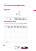
The device uses 4 main screens. 


The Program screen 


Use the 

Program

 screen to select a test program. 


Current program name (here 

NAME

)


Current program number (here 

001

)


Test type (here 

LEAK TEST


Access at startup of the device or by pressing several times 

Esc 

.


Key 

Name 

Function 


Up key 

Scrolls up or increases numerical values. 


Down key 

Scrolls down or decreases numerical values. 


OK 

Returns to the 

MAIN MENU

 screen or opens menus and options, 

validates parameters. 


Esc 

Returns to previous screen (until the 

Program

 screen), escapes 

without modifying parameters. 

Key 

Name 

Function 


Smart key 

Starts a measurement cycle (default, programmable). 

Содержание F670

Страница 1: ...ATEQ F670 Quick Start Guide...

Страница 2: ...Connectors on the back panel with all options 10 Power supply connectors 12 Digital links 12 Analog outputs 15 Digital inputs outputs 16 Pneumatic connectors 19 Pneumatics configuration 22 User interf...

Страница 3: ...ateq com cn T 86 21 6763 9508 F 86 21 6763 9528 ATEQ SYSTEMS ANALYSIS TAIWAN CO LTD NO 3 LAN 223 San Jia Dong Street 40642 TAICHUNG TAIWAN ateqtaiwan ateq com tw ateq com tw T 886 4 2437 5278 F 886 4...

Страница 4: ...d the user manual before using the device All electrical connections to the device must be equipped with safety systems fuses circuit breakers etc adapted to the needs and in accordance with the appli...

Страница 5: ...tions impurities must be prevented from being drawn into its internal components For this purpose we strongly recommend that a suitable airtight filter is installed between the part under test and the...

Страница 6: ...QSG_F670_363 00_EN_01_2021 02 09 6 42 Preamble ATEQ F670 AN UNIVERSAL LEAK TESTER ATEQ F670 is a leak detector that tests the airtightness of parts ATEQ F670 can memorise 128 different test programs...

Страница 7: ...by a cap 1 Device 2 Pressure sensor 3 Part under test 4 Differential pressure sensor 5 Reference part Desensitized test This mode is used for the measurement of large leaks when the reject level requ...

Страница 8: ...ent cycle is made of 4 main phases fill stabilization test dumping A Pressure auto zero additional phase 0 can be placed at the start or at the end of a cycle depending on the requirement of the opera...

Страница 9: ...t panel 1 Device name 2 Serial number 3 Display 4 Parameters lock key option 5 RS232 connector option 6 Mechanical regulator option 7 Cycle keys 8 Navigation keys 9 USB connectors 10 Mechanical regula...

Страница 10: ...QSG_F670_363 00_EN_01_2021 02 09 10 42 CONNECTORS ON THE BACK PANEL WITH ALL OPTIONS...

Страница 11: ...r option 14 Test part exhaust also for test pressure sensor auto zero 15 ATEQ Air supply energy information 16 Part number Serial number 17 P1 External back pressure connector option 18 T Test output...

Страница 12: ...KS PC USB connectors on front face USB connectors can be used for connecting miscellaneous compatible USB devices The USB connectors are located under the rubber cover 1 see figure 1 Rubber cover 2 US...

Страница 13: ...icenet connectors J5 J6 option M12 type connector 5 pins male connector J5 Devicenet input For connection to others ATEQ devices Pin number Signal 1 Not used 2 RXD data input 3 TXD data input 4 Not us...

Страница 14: ...connector 4 pins female connector J5 J6 Ethernet connector J5 J6 option Standard connection Ethernet TCP IP protocol One of these network protocols is available Ethernet IP Profinet Ethercat J5 Input...

Страница 15: ...M12 type connector 8 pins female connector J1 option Pin number Description 1 Ground pressure 2 0 10V DC pressure 3 Ground Pressure Diff 4 0 10V DC Pressure Diff 5 Signal contact event option 6 Ground...

Страница 16: ...tion Characteristics Inputs Activation 24 V DC Outputs Dry contacts 60 V AC DC max 200 mA max Pin number Inputs outputs Description 1 Input 1 RESET 2 24 V DC Common 3 Input 2 START 4 24 V DC Common 5...

Страница 17: ...the program number Pin number Inputs outputs Description 1 Input 8 Program selection from 33 to 64 programmable input 2 Input 9 Program selection from 65 to 128 programmable input Program number J9 J...

Страница 18: ...V DC Common outputs 1 2 3 2 Output 1 Open collector 3 Output 2 Open collector 4 Output 3 Open collector 5 24 V DC Common outputs 4 5 6 6 Output 4 Open collector 7 Output 5 Open collector 8 Output 6 Op...

Страница 19: ...ed by ATEQ Refer to Good practices and safety instructions section A specific filter may be necessary The air is supplied via the filter located on the back panel of the device Metal air filter The me...

Страница 20: ...ons must be air tight Test and reference outputs 1 Test connector 2 Reference connector 3 Not used 4 Exhaust output 5 Pressurization output Metallic fitting available for test 1 and reference 2 connec...

Страница 21: ...configuration 3 Optional fitting according to special configuration Pneumatic output 0 6 MPa 87 PSI option A and B automatic connectors option These connectors are used to drive pneumatic caps on the...

Страница 22: ...at a pressure range from 0 to 500 kPa 72 5 PSI Connection Option description Air supply 1 Connection of the air supply to the filter input 0 6 MPa 87 PSI Vacuum to 2 Connection of the vacuum option 3...

Страница 23: ...Connection of the regulator air supply to the filter input 1 2 MPa 174 PSI Air supply to 2 Connection of the air supply 0 6 MPa 87 PSI Vacuum to 3 Connection to the vacuum option 4 to 5 Connection of...

Страница 24: ...tor air supply to 2 Connection of the regulator air supply 2 MPa 290 PSI 3 to ATM Output to be left to the atmosphere exhaust of electronic regulator 7 to 4 Connection of the Test output to the Y valv...

Страница 25: ...ter input 0 6 MPa 87 PSI Regulator air supply to 2 Connection of the regulator air supply 2 MPa 290 PSI 3 to ATM Output to be left to the atmosphere exhaust of electronic regulator 7 to 4 Connection o...

Страница 26: ...y to the filter input 1 2 MPa 174 PSI Air supply to 2 Connection of the air supply 0 6 MPa 87 PSI Vacuum to 3 Connection to the vacuum option 4 to ATM Output to be left to the atmosphere to exhaust th...

Страница 27: ...ir blowing and temperatures variations Connection Option description Air supply to 1 Connection of the air supply to the filter input 0 6 MPa 87 PSI Vacuum to 2 Connection to the vacuum option 3 to 4...

Страница 28: ...r supply to the filter input 0 6 MPa 87 PSI Vacuum to 2 Connection to the vacuum option 3 to 4 Connection of the reference output to the reference part 5 to 6 Connection of the V1 output to the refere...

Страница 29: ...ction Option description Air supply to 1 Connection of the air supply to the filter input 0 6 MPa 87 PSI Vacuum to 2 Connection to the vacuum option 3 to 4 Connection of the reference output to the re...

Страница 30: ...he front panel 1 Display 2 Cycle keys 3 Navigation keys KEYS Cycle keys The cycle keys are used to start and to stop a measurement cycle Key Name Function Start On the Program screen starts a measurem...

Страница 31: ...gram screen Use the Program screen to select a test program 1 Current program name here NAME 2 Current program number here 001 3 Test type here LEAK TEST Access at startup of the device or by pressing...

Страница 32: ...asurement unit 7 when the standard conditions function is validated Refer to the Reference Manual The MAIN MENU screen The MAIN MENU screen gives access to different sections for managing the device a...

Страница 33: ...h last program used on screen PREPARING A PROGRAM Use this procedure to configure a new test program On the MAIN MENU screen ACCESSING THE PARAMETERS 1 Select PARAMETERS using the up down keys and the...

Страница 34: ...icon is displayed at the bottom of the screen you must insert the USB unlocking device or enter a password before modifying a parameter On the PARAMETERS screen of the program see Preparing a program...

Страница 35: ...screen STARTING A MEASUREMENT CYCLE 1 Press Start The cycle phases of the program are successively displayed FILL STABILIZATION TEST DUMP At the end of the cycle the results are displayed and READY a...

Страница 36: ...se the part with an infinite fill time Piezo auto zero Piezo auto zero Auto zero cycle on the piezo sensor AUTO VOL Automation volume Volume calculation for automatic program selection Label Special c...

Страница 37: ...for the test part Above this limit the part is considered as defective Ref FAIL Reference fail Reference part reject level FUNCTIONS Functions Access to additional functions Some parameters are displa...

Страница 38: ...E No Negative Replace negative value per 0 N TESTS N tests Repeats the test when the results get close to the reject level PEAK HOLD Peak hold Give as result the highest flow during the test time PR S...

Страница 39: ...process option Press UNIT Pressure unit by default for the new programs DUMP LEVEL Configuration of the minimum dump level pressure LINE P MIN Minimum level for checking line pressure option BLOW MODE...

Страница 40: ...al cycles to carry out device internal tests RESET PARA Parameters reset Reset to factory configuration FIELDBUS Fieldbus parameters Fieldbus information RESULTS menu In this section manage measuremen...

Страница 41: ...is section describes save and restore parameters on an external USB device Label Description Save parameters Save parameters on an external USB memory device for restoring later Restore parameters Res...

Страница 42: ...I Pneumatic air supply 0 to 0 5 MPa range Air supply 0 6 MPa 15 Pneumatic air supply 0 6 to 1 MPa range Regulator input 1 2 MPa 10 Valves supply 0 6 MPa 15 Pneumatic air supply 1 1 to 2 MPa range Regu...

Отзывы: