


UCE32100 User Manual
8
Mounting the UCE32100 Units
You can mount the UCE32100 units to the wall or on the DIN Rail. Before you
begin to mount the units, you will need to mount the brackets into the back of
the UCE32100 units.
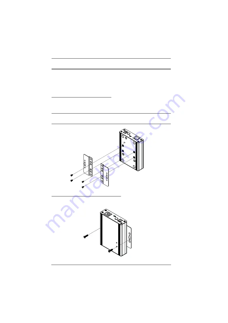
Mounting the UCE32100 Units
Screw the mounting brackets into the back of the units using the smaller screws
supplied in the Mounting Kit.
Note:If you do not use the supplied screws, the length of the shank (the
threaded portion) must not exceed 4.50mm.
Wall Mounting the UCE32100 Units
Screw the mounting brackets to a wall.