


UCE32100 User Manual
4
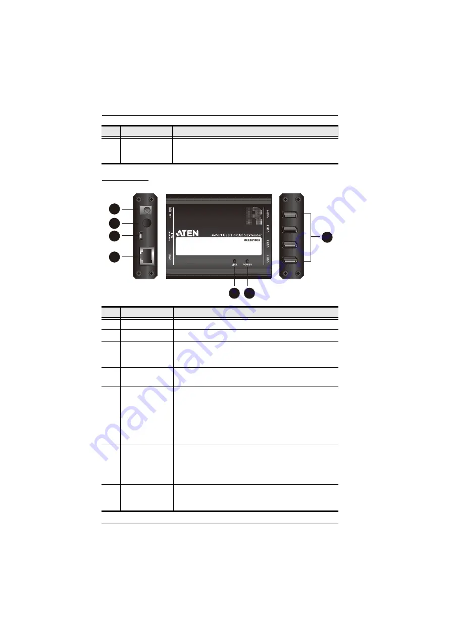
UCE32100R
7
USB 2.0 Type-B
Female Port
(Host)
Receives a USB Type-B male to Type-A male cable that
connects the UCE32100T to the computer in your setup.
No.
Component
Description
1
Power Jack
Receives the power adapter.
2
DC Jack Lock
Locks the Power Jack to avoid power cut or power shortage.
3
Firmware
Upgrade Port
(Micro USB)
This port is for firmware upgrade.
4
Link Port (RJ-45)
Receives a Cat 5/5e/6/7 cable that sends and transmits data
between the UCE32100R and the UCE32100T.
5
Link LED
(Amber)
On: To indicate that the USB connection between the
UCE32100T and the UCE32100R is stable.
Blink: To indicate that the data is being transmitted
between the UCE32100T and the UCE32100R.
Off: To indicate there is no connection between the
UCE32100T and the UCE32100R.
6
Power LED
(Green)
On: To indicate that the power is being supplied to the
unit.
Off: To indicate that there is no power being supplied to
the unit.
7
USB 2.0 Type-A
Female Ports
(USB peripherals)
Receive USB cables to connect to USB peripherals you
wish to access from the computer in your setup.
No.
Component
Description
4
1
2
3
7
5 6