Using PRO II internally
Like mounting a 3.5" floppy drive to your PC, PRO II comes
with 3 screw holes on each side for position adjustment.
Insert PRO II into one of empty 3.5" external drive bay of
your PC, align the PRO II front panel evenly with the computer
front bezel and apply screws to secure it into the place.
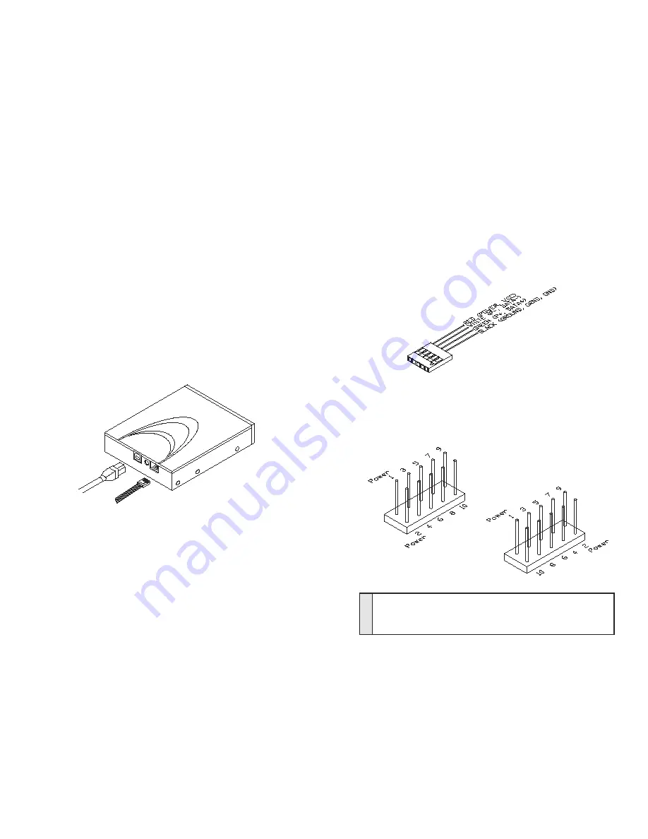
For internal cable connections, plug in the Internal USB cable
and power supply "Y" cable. Please refer to the following
diagram for connection to the PRO II .
Due to certain motherboard USB headers have different pin
layouts, it is possible that user needs to reconfigure the wire
pin assignments on the internal USB cable, in order to make
PRO II function properly. Following explains how to
reconfigure wire pin assignment.
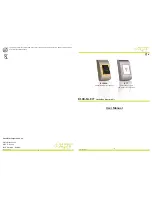
The Internal USB cable has 4 color wires on the end
that plugs in to the motherboard. The 4 color wires
are Red, White, Green and Black wires. The correct
wire assignments shall be:
Internal
USB cable
Internal Power Supply "Y" cable
Please refer to your motherboard manual or contact your
motherboard manufacturer for the USB header pin layout
information. Two of the most common layouts are as follow:
Red = Power or VCC
White = P- or Data-
Green = P+ or Data+
Black = Ground or GRND or GND
Example A
Example B
E
xa
m
ple
A
1. USB Power (or VCC or +5V) 2. USB Power (or VCC or +5V)
3. P-
4. P-
5. P+
6. P+
7. GND
8. GND
9. (Empty pin)
10. GND


