Druck PV 411 User Manual
Page 11
K258 Issue No. 1
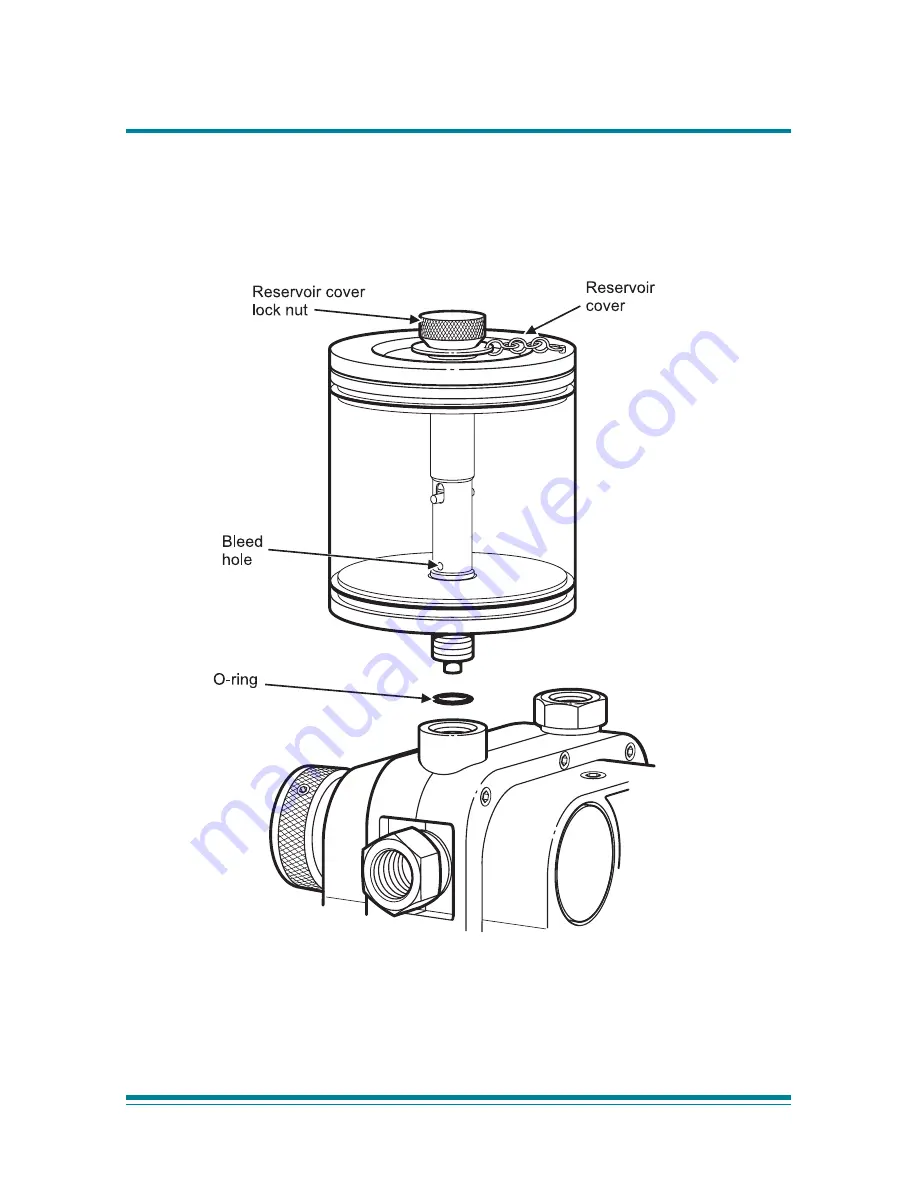
Figure 2, Fitting the Reservoir
Страница 1: ... is the property of Druck Limited and may not be copied or otherwise repro duced communicated in any way to third parties nor stored in any Data Processing System without the express written authorisation of Druck Limited Advanced Test Equipment Rentals www atecorp com 800 404 ATEC 2832 Established 1981 ...
Страница 2: ... the specification This manual contains safety and operating instructions which must be followed to make sure of safe operation and to keep the equipment in a safe condition The safety instructions are either warnings or cautions issued to protect the user and the equipment from injury or damage Use suitably qualified personnel and good engineering practice for all procedures in this manual Pressu...
Страница 3: ...imetre F degrees Fahrenheit inHg inches of mercury lbs pounds ISO International Standards Organisation kg kilogram m metre mbar millibar mm millimetre mmH2 O millimetres of water NPT National pipe thread PRV pressure relief valve psi pounds per square inch PTFE polytetraflouroethylene SAE Society of Automotive Engineers UUT Unit under test Symbols The following symbols mark this equipment Read the...
Страница 4: ...atic Operation 7 Volume adjuster 7 Generating pneumatic pressure and vacuum 8 Pressure 8 Vacuum 8 Hydraulic Operation 10 Fluid reservoir 10 Fitting 12 Filling 12 Priming the system 13 Vacuum priming 13 Pre filling 14 Setting pressure relief valve 14 Generating hydraulic pressure 15 Multimedia 16 Flushing 16 Fault finding 17 Approved service agents 18 Annex A Returned Goods Procedure 19 ILLUSTRATIO...
Страница 5: ...ween selections of pressure and vacuum Operating the scissor action handles provides the pumping stroke for pressure generation A volume adjuster allows small adjustments of the system pressure Hydraulic pump Figure 1 The selector valve vents the system to the reservoir between selections of pressure and vacuum used in the priming process The volume adjuster generates the required system pressure ...
Страница 6: ...Druck PV 411 User Manual K258 Issue No 1 Page 2 Figure 1 General view ...
Страница 7: ...d Demineralised water or mineral based oils Hydraulic fluids must be compatible with Stainless steel anodised aluminium nitrile rubber PTFE polypropylene delrin acrylic and nylon Pressure connections 1 4 BSP parallel female Weight approximate 1 1 kg Dimensions Length 260 mm Width 135 mm Depth 95 mm This value assumes atmospheric pressure at 1 bar and will vary depending on atmospheric pressure ...
Страница 8: ... STATED IN THE SPECIFICATION 4 OBSERVE THE RELEVANT HEALTH AND SAFETY PRECAUTIONS Note Wherever possible use o ring seals in the connection ports this is the recommended method of sealing Pressure vacuum Configuration Figure 1 In pressure mode air fluid is drawn in through the inlet port on the top of the pump and forced out through the two outlet ports In vacuum mode the air fluid flow is reverse...
Страница 9: ... 1 4 BSP swivel adaptor connects with a range of fixed adaptors Using the knurled grip feature hand tighten clockwise the swivel adaptor until it is fully inserted Swivel pump head The pump head swivels through 140 providing optimum viewing angle and bench top operation Placing the pump on the bench allows greater force to be applied to the scissor action handles Internal stops prevent further rot...
Страница 10: ...MAGING THE INSTRUMENT UNDER TEST BY USING THE VOLUME ADJUSTER TO RELEASE HYDRAULIC PRESSURE Scissor action Handles Limit Adjuster Turning the adjuster anti clockwise reduces the stroke turning the limit adjuster clockwise increases the stroke For maximum pneumatic pressure generation turn the limit adjuster fully clockwise ...
Страница 11: ...f the generated pressure can be made Using the scissor action handles generate the approximate pressure then turn the volume adjuster clockwise in to increase the pressure or turn the volume adjuster anti clockwise out to decrease the pressure Vacuum Turn the selector valve fully anti clockwise out position Turn the volume adjuster to the mid position In this position fine adjustments of the gener...
Страница 12: ...tor valve fully clockwise in position 2 Operate the scissor action handles to generate the approximate pressure allow time for thermal stabilization 3 If necessary use the volume adjuster to adjust the required pressure 4 After attaining the required pressure operate the scissor action handles to generate a higher pressure Alternatively vent the pressure to atmosphere by slowly turning anti clockw...
Страница 13: ...red vacuum operate the scissor action handles to generate a higher vacuum Alternatively vent atmosphere into the vacuum by slowly turning anti clockwise the selector valve to the centre position After completion depressurize the pump and disconnect from the pipes and equipment ...
Страница 14: ...d Reservoir Figure 2 The main body of the reservoir is transparent acrylic providing a clear view of the contents The reservoir can be removed from the pump without the need to empty the fluid a self sealing connection prevents leakage The spring loaded top cover seals under atmospheric pressure conditions but vents excess internal pressure harmlessly in the event of inadvertent pressurization The...
Страница 15: ...Druck PV 411 User Manual Page 11 K258 Issue No 1 Figure 2 Fitting the Reservoir ...
Страница 16: ...ralised water is used to test the pump at manufacture On shipment there will be traces of demineralised water in the system Filling Unscrew the reservoir cover lock nut and remove the reservoir cover Using clean recommended fluid fill the reservoir to approximately 2 3 full Refit the reservoir cover and re tighten the reservoir cover lock nut Connect the required pipes and equipment to the outlet ...
Страница 17: ... bleed hole in fluid Do not allow air to enter the system through this bleed hole Vacuum priming Figure 2 Connect the equipment as detailed on page 5 Air can be removed using the vacuum facility on the pump Note This method should not be used with vacuum sensitive equipment Turn selector valve fully out anti clockwise vacuum position Pump until bubbles stop appearing in the reservoir this generate...
Страница 18: ...e on the UUT If necessary top up the reservoir to the 2 3 level with clean fluid Secure the reservoir cover by tightening the reservoir cover lock nut The pump and connected system is ready for use Setting Pressure Relief Valve Figure 1 The pressure relief valve PRV can be set at pressures from 30 to 700 bar If the system pressure exceeds the set pressure the PRV opens and vents fluid through the ...
Страница 19: ...lume adjuster fully out anti clockwise Close the selector valve Use the scissor action handles to generate the initial pressure Then turn the volume adjuster clockwise to generate the required pressure allow time for thermal stabilization To reduce the pressure turn the volume adjuster out anti clockwise to the required pressure After completion turn the volume adjuster fully out anti clockwise an...
Страница 20: ...crew and remove the reservoir Invert the pump and using the vacuum selection operate the scissor action handles to draw residual fluid out through the inlet port WARNING WHEN OUTLET PORTS ARE OPEN AND WITH THE SELECTOR VALVE SET TO PRESSURE OPERATING THE SCISSOR ACTION HANDLES RAPIDLY EXPELS FLUID Pneumatic venting after fluid use can generate a fluid mist spray out of the inlet port Flushing If n...
Страница 21: ...ize 3 Check the adaptors flexible pipe and connections between the pump and equipment under test for leaks Tighten any loose joints and replace any seals that are worn or damaged 4 In hydraulic mode if the volume adjuster can be wound fully in but maximum pressure cannot be achieved there is probably air trapped in the system Re prime and repeat If for any reason a fault occurs within the pump it ...
Страница 22: ...7100 Fax 0116 231 7103 USA Druck Incorporated 4 Dunham Drive New Fairfield Connecticut 06812 U S A Tel 203 746 0400 Fax 203 746 2494 France Druck SA 19 Rue Maurice Pellerin 92600 Asnières France Tel 1 43 34 24 75 Fax 1 43 34 86 08 Germany Druck Messtechnik GmbH Auf dem Hohenstein 7 61231 Bad Nauheim Germany Tel 6032 93300 Fax 6032 933080 Holland Druck Nederland b v Postbus 232 Zuideinde 37 2991 Lj...
Страница 23: ...ation RGA number providing the following information Product i e PV 411 Pressure medium i e pneumatic hydraulic Serial number Details of defect work to be undertaken Operating conditions Safety Precautions You must also tell us if the product has been in contact with anything hazardous or toxic and the relevant COSH references and precautions to be taken when handling Important notice Service by u...
Страница 24: ......