background image

9

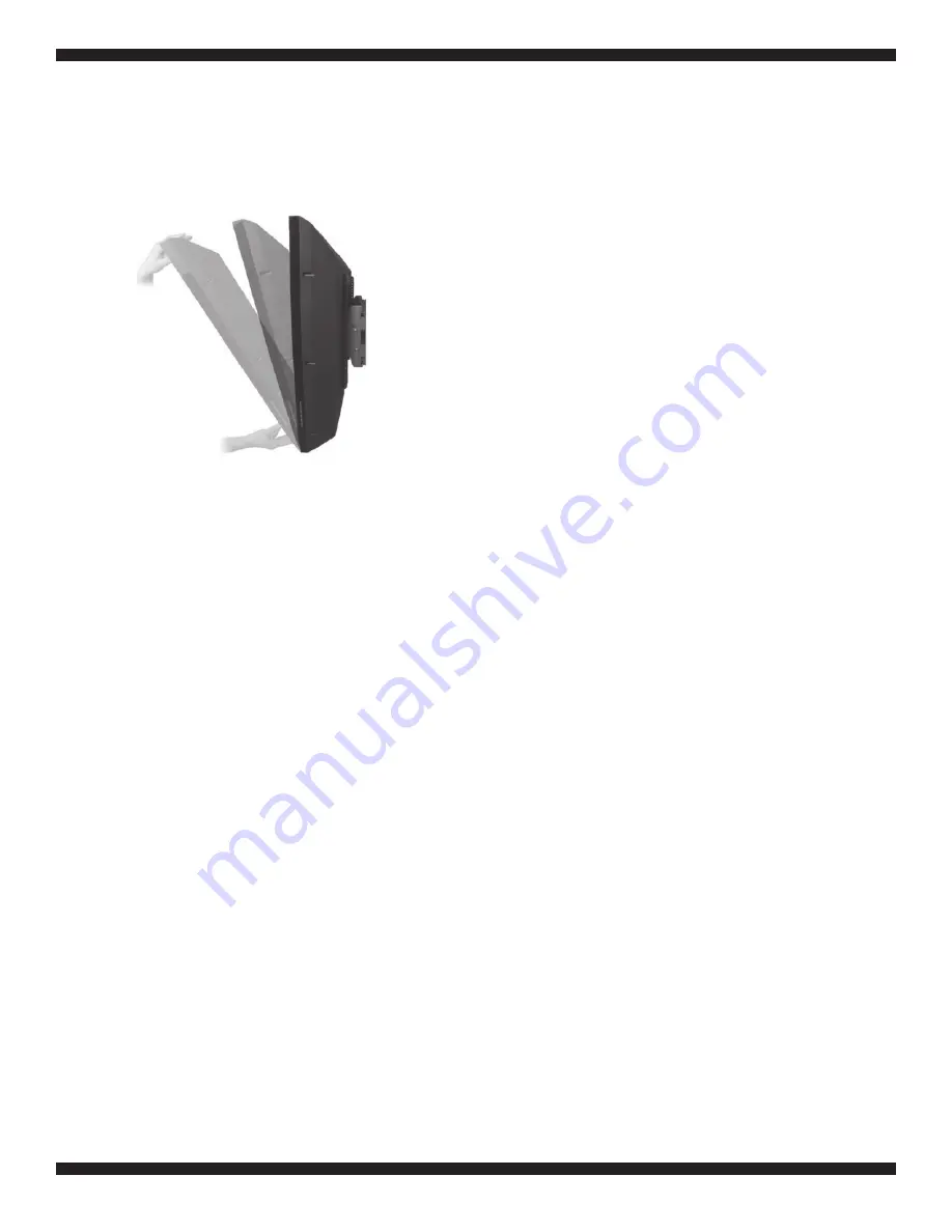
Fig. 5

Step 5: Adjusting the tilt angle

This patented design features an unique tilt angle mechanism that can easily be adjusted by just one 

person. No tools are required for this step. As shown in Fig. 5, grasp the top and bottom of the mount-

ed flat panel and gently pull the top of the flat panel toward you or back to adjust the viewing angle.

After mounting, if the TV does not stay in your preferred 

viewing

 angle there is not enough tension 

on the two screws found on the inner side of each “angle-free” 

bracket. Follow the six steps below to

adjust (tighten) the tension of the bracket screws to prevent this issue

.

1.  Carefully 

remove

 the TV from the wall mount bars and place the screen face down on a 

flat

 surface 

that is clean and without objects of any 

kind.

 The rear of the 

flat

 panel with the “angle-free” mount 

brackets attached is facing upward towards the ceiling. 

2.  Use a regular slotted 

screwdriver

 to 

remove

 the four 

black

 rubber screw “caps” found on the inner 

side of each bracket.

3.  Use the 

Box

 wrench (6) to tighten all four of these nuts (two nuts on each 

bracket)

 1/4 turn to the 

right. 

After tightening, replace the black plastic 

c

aps over each scre

w.

4.  Carefully lift up the TV and properly attach the 

brackets

 to the mount bar and secure the safety 

latches

5.  Adjust the “angle-free” tilt to your proper 

viewing

 position and without letting go of the TV, lessen 

your hand pressure to see if the angle tilt is properly held in place by the mount. If additional tension 

is still required, repeat steps 1 – 5. Do not 

over-tighten

 these nuts or the “angle-free” tilt adjustment 

will not function at all.

6.  Once the proper tension is 

achieved,

 replace the 

black

 rubber caps on the 

exposed

 ends of the 

screw/nuts

Mount Reference Dimensions

Adjustable bracket spacing: 200 – 700 mm 


   (7.87 in – 27.55 in)

Bracket height: 530 mm (20.86 in) 

Bracket frame height: 180 mm (7.08 in)

Bracket frame length: 820 mm (32.28 in)

In some cases depending on the weight of your TV

, the bracket angle tension may require a one-

time adjustment.

Содержание A570TS

Страница 1: ...he maximum weight indicated may result in instability and cause possible injury READ THIS FIRST Read this entire manual Do not attempt to install this product if you do not understand the taching this mount to Check all the parts carefully to make sure there are no missing or damaged parts Improper installation may result in damage to your TV property and personal injury Easy installation Built in...

Страница 2: ...cure assembly please contact a professional Don t let children climb on or play with mounts or TVs Remember that children can become excited while watching a program especially on a larger than life TV Make sure to place or install the TV wall mount where it cannot be pushed pulled on or knocked down Make sure that you route all cords and cables so that they cannot be pulled or grabbed by curi ous...

Страница 3: ...Square washers Long bolts Wall anchors Long bolt washers Spacers Description Wall Mount Left bracket M8 25mm bolts G 4 4 4 4 H ID Description Qty Cable cover Box Wrench M4x20mm bolts ID 1 2 4 D 3 5 E F 1 1 1 4 1 2 4 4 Qty A 6 1 4 Security safety bolts C B 4 4 M4x30mm bolts M5x20mm bolts M5x30mm bolts M6x25mm bolts M6x40mm bolts M8 45mm bolts 4 12 N O M4 M5 washers M6 M8 washers M ...

Страница 4: ...er according to the size depth and position of the mounting holes in your TV For correct installation install the brackets with the hook on each bracket facing down Install the bolts spacers and square washers in accordance with the following If your television has a straight back spacers are not required Use the selected bolts A H and square washers I to install the bracket directly on the back o...

Страница 5: ...uired Install the spacers M between the display and the bracket as shown in Fig 1b Then use the appropriately selected bolts A H applicable to your TV and the square washers I to install the brack ets with spacers to the back of the television Make sure that the two brackets are equal in height and are level Once the brackets are aligned securely tighten the bolts Fig 1b If neccessary use addi tio...

Страница 6: ...er If distance a is 8 to 13 feet 2 4 to 4 meters distance b is about 3 feet 0 9 meter If distance a is 14 to 17 feet 4 3 to 5 2 meters distance b is about 4 feet 1 2 meters Add the eye level height plus b to get the ideal height of the center of the television display After determining the ideal height on the wall for your television follow the mounting instructions for your type of wall construct...

Страница 7: ...o not use wall anchors in wood stud walls 5 Use the built in level to level the wall mount Fig 3d repositioning as necessary then securely tighten the bolts Fig 3b Fig 3c Fig 3d Concrete Walls to mark the location of all four mounting holes on the wall Make sure that the mounting holes are level and are parallel 2 Use a 10 mm drill bit to pre drill four holes at least 50 mm 2 inches deep at the ma...

Страница 8: ...is securely installed can result in equipment damage or personal injury 1 Lift the television display with the brackets securely attached to the wall mount 2 Hook the top of brackets over the top bar of the wall mount Fig 4a 3 Rotate the display to let the brackets hook over the bottom bar of the mount Then install a safety bolt 5 into the lower end of each bracket to lock the television in place ...

Страница 9: ...iver to remove the four black rubber screw caps found on the inner side of each bracket 3 Use the Box wrench 6 to tighten all four of these nuts two nuts on each bracket 1 4 turn to the right After tightening replace the black plastic caps over each screw 4 Carefully lift up the TV and properly attach the brackets to the mount bar and secure the safety latches 5 Adjust the angle free tilt to your ...

Страница 10: ...ist located in the Instruction Manual included with the product This warranty applies under conditions of normal use This warranty does not cover any product which has been subject to damage due to improper assembly or disassembly products which were not assembled installed used or maintained in accordance with the product assembly instructions warnings acts of nature misuse neglect accidents abus...

Страница 11: ...11 ...

Страница 12: ...Schoenfeld International Inc and ATEC 5001 American Boulevard West Suite 275 Bloomington MN 55437 Schoenfeld International Inc 2014 PN A570TS Rev 1 2 January 2014 ...

Отзывы: