Rev.02-06/25/12
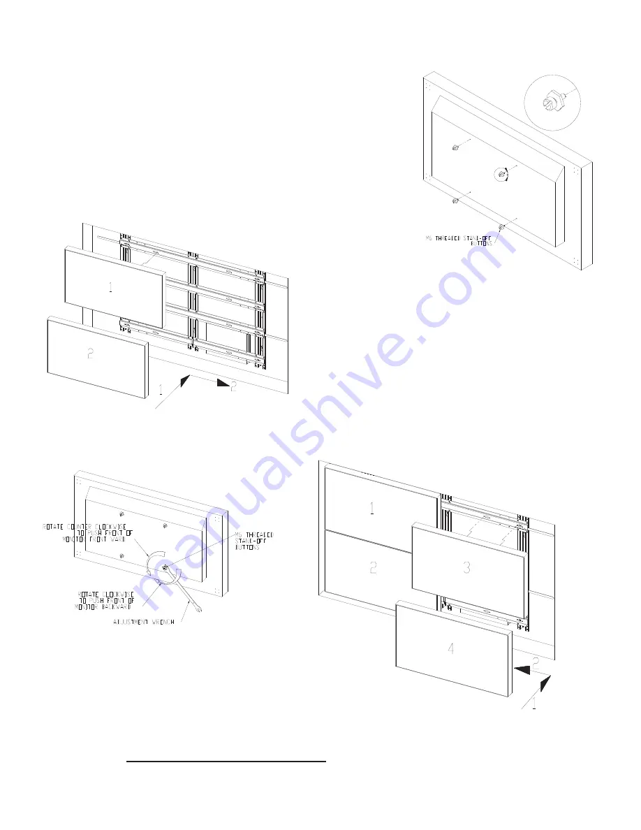
Figure 9
Figure 11
Step 10: M6 threaded stand-off buttons to LCD monitors
Thread four M6 threaded standoff-buttons into the outer VESA mounting holes at the
back of each monitor
(Figure 8).
Step 11: Install Monitors to the Left Column
Starting with the upper left monitor, connect power and signal wires to each monitor.
Lift up locking arms on the left side of the frame. Align the four stand-off buttons with
the four large slots in the H-slats then slide the monitor from left to right until it stops
then pull down the locking arm to lock into place
(Figure 9).
Repeat step 11 for the
lower monitors.
Step 12:
Note on
alignment:
While installing
monitors, check
for front and side
alignment of the
monitors. The
surfaces of all monitors must be aligned and flush to each other. If
one or more screens are tilted more than others use the adjustment
bracket to reach the hex portion of the M6 threaded buttons at the
rear of the monitor and rotate counter clockwise to pull the front of
the monitor forward or rotate clockwise to push it back ward. If
access to the rear is not accessible remove the screen(s) and,
depending whether the monitor needs to be tilted forward or
backward rotate the buttons using the adjustment wrench or a flat
head screw driver
(Figure 10).
Reinstall and recheck surface
alignments. Repeat where necessary.
Step 13:
Install Right Column Monitors
Starting with the upper right monitor, connect power and
signal wires to each monitor. Lift up the locking arms on the right
side of the frame. Align the four stand-off buttons with the four large
slots in the H-slats then slide the monitor from right to left until it
stops then pull down the locking arm to lock into place
(Figure 11).
Repeat step 12 for the lower monitors. Check for front
and side alignments.
Refer to Step 12 for front alignment process.
Figure 8
Figure 10


