background image

9-888-902-41

OLED TV

Sony EMCS (Malaysia) Sdn. Bhd., HES-M

© 2022.05

ORIGINAL MANUAL ISSUE DATE: 2022.05

Conditions of Use:
(1) Please use this information only for the purpose of performing repair and recycling Sony products. Using this information

for any purpose other than the purpose described foregoing is forbidden.

(2) Do not copy, replicate, reproduce, alter, translate, transmit, sell, lease, or distribute this information in whole or in part

without the prior written permission of the author.

Revision of Information:
This information may be changed or updated at any time without any prior notice. Please confirm that this information is up-to-
date before using it.

Dismantling Information forUse      

by ProfessionalRecyclers

Model:

XR-55A95K

XR-65A95K

Содержание XR-55A95K

Страница 1: ...he purpose described foregoing is forbidden 2 Do not copy replicate reproduce alter translate transmit sell lease or distribute this information in whole or in part without the prior written permission of the author Revision of Information This information may be changed or updated at any time without any prior notice Please confirm that this information is up to date before using it Dismantling I...

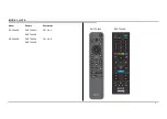
Страница 2: ...2 MODEL LISTS Model Remote Destination XR 55A95K RMF TX900U CEI UKA RMT TX440E XR 65A95K RMF TX900U CEI UKA RMT TX440E RMF TX900U RMT TX440E ...

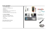
Страница 3: ...or remove replace details 2 OPTIONAL EQUIPMENTS i Screwdriver e g 0 Phillips Screwdriver ii Parts Tray for loose screws and small items iii Flashlight iv Service Manual For Surface Mounted Parts Connectors Hot Air type soldering iron is needed Thickness approx 1 5mm Diameter 20 25mm wrap in tape L 50mm Plastic or Metal Ruler In case of Metal ruler wrap in tape L 50mm for prevent scratches TOOLS EQ...

Страница 4: ...d to de energize the phase conductors Except AC ADAPTOR Because it does not carry out replacing an internal fuse 4 CARRYING THE TV be sure to follow these guidelines to protect your property and avoid causing serious injury Carry the TV with an adequate number of people larger size TVs require two or more people Correct hand placement while carrying the TV is very important for safety and to avoid...

Страница 5: ...image retention Content with black bars either on the top and bottom and or the left and right sides of the screen for example Letterboxed 4 3 screen Standard definition Static images such as photos Video games that might have static content in some part of the screen On screen menus program guides channel logos etc Static content from applications On screen tickers such as those used for news and...

Страница 6: ...mage retention is very noticeable or you see the following message Panel refresh did not finish Caution The Panel refresh function may affect the panel As a reference perform the Panel refresh only once a year do not perform it more than once a year as it may affect the usable life of the panel Panel refresh takes about one hour to complete A white line may be displayed on the screen during the Pa...

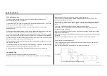
Страница 7: ...r safety reasons repairing the Power board and or Inverter board is prohibited 1 4 Leakage Test To protect electric shock when customer touch the terminal Leakage current can be measured by V Voltmeter or oscilloscope r m s or peak reading Stabilized power supply instrument and isolated voltage transformer Use too much current capacity and isolated voltage transformer does not need to use stabiliz...

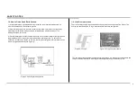
Страница 8: ...hot side of the receptacle and the retaining screw Try both slots if necessary to locate the hot side on the line the lamp should light at normal brilliance if the screw is at ground potential see Figure 3 Figure 3 Checking for earth ground The servicing of these boards requires special precautions It is strongly recommended to use Lead Free Solder material in order to guarantee optimal quality of...

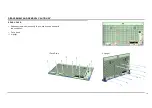
Страница 9: ...D REMOVAL CAUTION 55 Notes If the table top style is the front position change it to the back position Front position Back position Remove the SET from the stand flip it over and insert it into the stand and then screw tightening ...

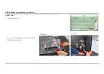
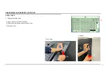
Страница 10: ...10 1 Release screw which is quantity 10 pcs and it can be done with two conditions i Face down ii Upright REAR COVER ii Upright i Face Down DISASSEMBLY AND REMOVAL CAUTION 55 ...

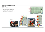
Страница 11: ...11 Insert hand into the gap and release the Rear Cover Release hooks from 1 to 5 REAR COVER 2 Release Recess Hook i Face Down ii Upright DISASSEMBLY AND REMOVAL CAUTION 55 ...

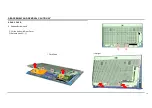
Страница 12: ... 12 3 Release Right Side Hook Lightly press the left side of the hook Insert hand into the gap and lift the Rear Cover Release 1 hook REAR COVER 1 2 i Face Down ii Upright DISASSEMBLY AND REMOVAL CAUTION 55 ...

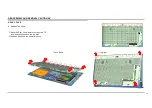
Страница 13: ...and into the gap and lift the Rear Cover Lightly press the right side of the hook Insert hand into the gap and lift the Rear Cover and release hook Release 3 hooks in order from the bottom 1 2 i i Face Down ii Upright DISASSEMBLY AND REMOVAL CAUTION 55 ...

Страница 14: ...14 5 Release Bottom Hook Lift the bottom of Rear Cover Release Hook REAR COVER i Face Down ii Upright DISASSEMBLY AND REMOVAL CAUTION 55 ...

Страница 15: ...EAR COVER 6 Release Top Hook Move the Rear Cover toward the top of the TV and remove the hook on the top side Release 8 hooks in the same time hook i Face Down ii Upright DISASSEMBLY AND REMOVAL CAUTION 55 ...

Страница 16: ...ositioning REAR COVER Position to press 37 37 40 205 165 160 160 165 205 185 185 145 135 108 112 15 104 64 64 11 160 19 40 Panel Outline Panel Outline Panel Outline Panel Outline DISASSEMBLY AND REMOVAL CAUTION 55 ...

Страница 17: ... surface before disassembly and assembly of parts and shaded parts are critical for safety Replace only with part number specified Parts contain confidential information Strictly follow the instruction whenever the components are repaired and or replaced EXPLODED VIEW PART LIST 55 1 7 2 3 4 5 6 REF NO PART NO DESCRIPTION REMARKS 1 5 034 190 01 COVER STAND L L DER 2 5 034 191 01 COVER STAND R L DER...

Страница 18: ...ce Remove screws before disassembly Unplug connectors before disassembly Place the TV set facing downwards on a stable level surface before disassembly and assembly of parts and shaded parts are critical for safety Replace only with part number specified Parts contain confidential information Strictly follow the instruction whenever the components are repaired and or replaced EXPLODED VIEW PART LI...

Страница 19: ...t Board incl capacitors 20 1 013 517 11 G212 STATIC CONVERTER TV Internal Power Supply 29 A 5045 536 A P MOD S55FF1 SVC Liquid Crystal Display 1 912 832 11 POWER SUPPLY CORD SET EU CEI Cable 1 002 007 11 C17 AC CORD SET SWISS CEI 1 001 115 12 POWER SUPPLY CORD SET UK UKA EXPLODED VIEW PART LIST 55 OTHER PART ...

Страница 20: ...14 818 11 FLEXIBLE FLAT CABLE 25P CN102 H CN1200 B 1 4 1 014 817 11 FLEXIBLE FLAT CABLE 20P CN3803 B BT 1 5 1 014 819 11 FLEXIBLE FLAT CABLE 25P C CN3804 B CAMERA 1 6 1 014 898 11 CONNECTOR ASSY 30P CN6601 G J105 TCON 1 7 1 014 899 11 CONNECTOR ASSY 20P CN1700 B CN6401 G 1 8 1 014 900 11 CONNECTOR ASSY 10P SP CN6603 B SP 1 9 1 972 625 11 CONNECTOR ASSY 4P CN6605 B CIN 1 1 2 3 6 7 1 2 3 4 6 7 5 9 8...

Страница 21: ...D REMOVAL CAUTION 65 Notes If the table top style is the front position change it to the back position Front position Back position Remove the SET from the stand flip it over and insert it into the stand and then screw tightening ...

Страница 22: ...22 REAR COVER DISASSEMBLY AND REMOVAL CAUTION 65 1 Release screw which is quantity 10 pcs and it can be done with two conditions i Face down ii Upright i Face Down ii Upright ...

Страница 23: ...23 REAR COVER DISASSEMBLY AND REMOVAL CAUTION 65 Insert hand into the gap and release the Rear Cover Release hooks from 1 to 5 2 Release Recess Hook i Face Down ii Upright ...

Страница 24: ...SASSEMBLY AND REMOVAL CAUTION 65 3 Release Bottom Hook Press the corner of the recess Insert hand into the gap and lift the Rear Cover Release the hook Then repeat step 1 to 3 with second screw 2 1 4 i Face Down ii Upright ...

Страница 25: ... 25 REAR COVER DISASSEMBLY AND REMOVAL CAUTION 65 4 Release Side Hooks Insert hand into the gap and lift the Rear Cover Release the hooks in order from the bottom i Face Down ii Upright ...

Страница 26: ...DISASSEMBLY AND REMOVAL CAUTION 65 5 Release Top Hooks Lift the bottom of Rear Cover Move the Rear Cover toward the top of the TV and remove the hook on the top side 10 places at the same time i Face Down ii Upright ...

Страница 27: ...SEMBLY AND REMOVAL CAUTION 65 6 Hooks Positioning Position to press 55 52 52 55 239 79 193 193 193 193 239 152 152 155 145 100 112 25 104 97 97 23 160 12 155 39 145 Panel Outline Panel Outline Panel Outline Panel Outline ...

Страница 28: ...rface before disassembly and assembly of parts and shaded parts are critical for safety Replace only with part number specified Parts contain confidential information Strictly follow the instruction whenever the components are repaired and or replaced 1 7 2 3 4 5 6 EXPLODED VIEW PART LIST 65 REF NO PART NO DESCRIPTION REMARKS 1 5 034 192 01 COVER STAND L 2L DER 2 5 034 193 01 COVER STAND R 2L DER ...

Страница 29: ...nce Remove screws before disassembly Unplug connectors before disassembly Place the TV set facing downwards on a stable level surface before disassembly and assembly of parts and shaded parts are critical for safety Replace only with part number specified Parts contain confidential information Strictly follow the instruction whenever the components are repaired and or replaced Stand 29 25 27 26 1 ...

Страница 30: ...ERTER TV 28 A 5045 537 A P MOD S65FF1 SVC SET PART LIST 30 Printed Circuit Board incl capacitors Internal Power Supply EXPLODED VIEW PART LIST 65 Liquid Crystal Display 1 002 007 11 C17 AC CORD SET SWISS CEI 1 912 832 11 POWER SUPPLY CORD SET EU CEI 1 001 115 12 POWER SUPPLY CORD SET UK UKA Cable OTHERS PART ...

Страница 31: ...T CABLE 25P CN102 H CN1200 B 1 4 1 014 822 11 FLEXIBLE FLAT CABLE 20P CN3803 B BT 1 5 1 014 824 11 FLEXIBLE FLAT CABLE 25P C CN3804 B CAMERA 1 6 1 014 898 11 CONNECTOR ASSY 30P CN6601 G J105 TCON 1 7 1 014 899 11 CONNECTOR ASSY 20P CN1700 B CN6401 G 1 8 1 014 901 11 CONNECTOR ASSY 10P SP CN6603 B SP 1 9 1 972 625 11 CONNECTOR ASSY 4P CN6605 B CIN 1 1 2 3 4 5 9 8 6 7 EXPLODED VIEW PART LIST 65 ...

Страница 32: ...9 888 902 41 Sony EMCS Malaysia Sdn Bhd HES M English 2022 05 ...

Отзывы: