


8
V
ision
R
ecorder
6. C
lick
OK
. I
f
the
C
om
port
is
not
free
,
choose
another
port
by
selecting
F
ile
>
P
roperties
>
and
selecting
the
corresponding
COM
port
,
and
then
click
OK
.
N
ote
:
C
onfigure
the
COM
properties
as
follow
:
B
its
per
second
- 9600;
D
ata
bits
- 8;
P
arity
- N
one
;
S
top
bits
- 1;
F
low
control
- N
one
,
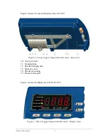
V
iewing
I
nformation
on
an
E
xternal
PC
T
o
view
information
from
the
AT-VLT
on
an
external
PC:
1. C
onnect
an
RS-232
cable
from
the
PC
to
the
RS-232
port
(
item
2
in
F
igure
6).
2. O
n
the
PC,
open
the
AT-VLT H
yper
T
erminal
connection
program
. T
o
open
it
,
select
S
tart
> P
rograms
> A
ccessories
> C
ommunications
> H
yper
T
erminal
and
double
-
click
the
AT-VLT H
yper
T
erminal
icon
that
you
previously
created
(
refer
to
E
stablishing
a
N
ew
H
yper
T
erminal
C
onnection
on
page
7).
T
he
AT-VLT H
yper
T
erminal
window
on
the
PC
displays
message
lines
according
to
the
sampling
rate
. T
he
H
yper
T
erminal
displays
whatever
information
the
AT-VLT
prints
,
both
manually
and
automatically
. F
or
information
on
printing
manually
,
refer
to
P
rinting
on
page
11. F
or
information
on
printing
automatically
,
refer
to
C
onfiguring
P
rint
S
ettings
on
page
18.
N
otes
:
T
o
capture
lines
one
after
the
other
,
select
F
ile
>
P
roperties
and
select
the
S
etting
tab
. U
nder
ASCII S
etup
,
select
A
ppend
line
feed
to
incoming
line
ends
.
T
o
capture
the
data
to
a
file
,
select
T
ransfer
>
C
apture
T
ext
. E
nter
the
file
name
and
click
S
tart
.
W
hen
the
format
is
configured
as
graph
,
only
the
current
temperature
and
the
alarm
range
appear
in
H
yper
T
erminal
. O
n
every
12
th
row
,
the
data
is
displayed
in
full
text
format
.
P
O
W
ER
T
his
section
explains
the
AT-VLT
’s
power
requirements
and
backup
battery
operation
capability
,
and
explains
how
to
install
or
replace
batteries
.
P
ower
S
ource
T
he
AT-VLT
uses
a
12V AC/DC
power
supply
. W
hen
the
AT-VLT
is
using
the
main
power
supply
,
the
P
ower
LED
is
lit
green
.


