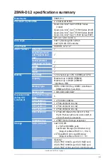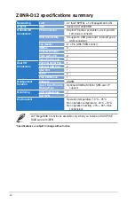
2-4
Chapter 2: Hardware information
2.2.4
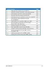
Layout contents
Slots / Sockets
Page
1.
CPU sockets
2-6
2.
DDR3 DIMM sockets
2-11
3.
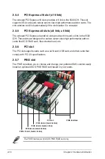
PCI Express x16 slot (x16 link)
2-16
4.
PCI Express x8 slots (x8 link; x4 link)
2-16
5.
PCI slot
2-16
6.
PIKE slot
2-16
Jumpers
Page
1.
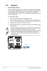
Clear RTC RAM (CLRTC1)
2-18
2.
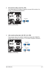
VGA controller setting (3-pin VGA_SW1)
2-19
3.
LAN controller setting (3-pin LAN_SW1, LAN_SW2)
2-19
4.
iBTN RAID setting (3-pin IBTN_SEL1)
2-20
5.
RAID configuration utility selection (3-pin RAID_SEL1)
2-20
6.
Force BIOS recovery setting (3-pin RECOVERY1)
2-21
7.
Fan controller setting (3-pin FAN_SEL1)
2-22
8.
DDR3 voltage setting (4-pin LVDDR3_SEL1/2)
2-22
Rear panel connectors
Page
1.
PS/2 mouse port (green)
2-23
2.
RJ-45 port for iKVM
2-23
3.
PS/2 keyboard port (purple)
2-23
4.
USB 2.0 ports 1 and 2
2-23
5.
Serial (COM1) port
2-23
6.
Video Graphics Adapter port
2-23
7.
LAN 1 (RJ-45) ports
2-23
8.
LAN 2 (RJ-45) ports
2-23
Содержание Z8NR-D12 - Motherboard - SSI EEB 3.61
Страница 1: ...Motherboard Z8NR D12 ...
Страница 13: ...1 Product introduction This chapter describes the motherboard features and the new technologies it supports ...
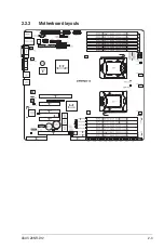
Страница 23: ...ASUS Z8NR D12 2 3 2 2 3 Motherboard layouts ...
Страница 52: ...2 32 Chapter 2 Hardware information ...
Страница 53: ...3 Powering up This chapter describes the power up sequence and ways of shutting down the system ...
Страница 54: ...ASUS Z8NR D12 Chapter summary 3 3 1 Starting up for the first time 3 1 3 2 Turning off the computer 3 2 ...
Страница 143: ...ASUS Z8NR D12 6 15 8 Follow the screen instructions to complete installation 9 When finished press Finish to continue ...
Страница 148: ...6 20 Chapter 6 Driver installation ...
Страница 150: ...Appendix summary A ASUS Z8NR D12 A 1 Z8NR D12 model block diagram A 1 ...
Страница 151: ...ASUS Z8NR D12 A 1 A 1 Z8NR D12 model block diagram ...
Страница 152: ...A 2 Appendix A Reference information ...


