background image

5-22

Chapter 5: BIOS setup

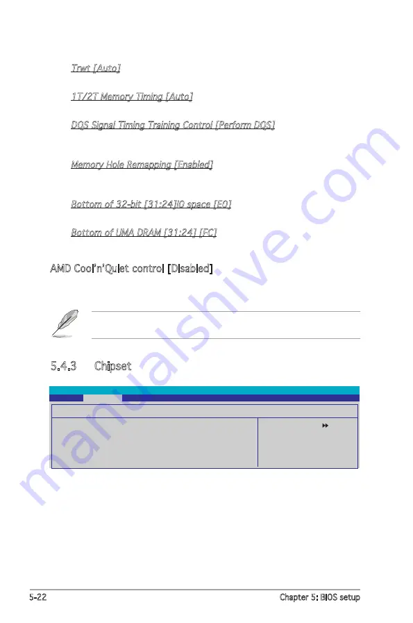
AMD Cool’n’Quiet control [Disabled]

Allows you to disable or set the AMD Cool ‘n’ Quiet!TM Technology feature. 

Configuration options: [Auto] [Disabled]

This feature requires the AMD CPU heatsink, fan assembly with monitor 

chip and BIOS utility. 

5.4.3  Chipset

Select Menu

Item Specific Help

Select Frame Buffer Size 

for Onboard Graphic

Phoenix-Award BIOS CMOS Setup Utility


Advanced


Chipset


Frame Buffer Size 

[32M]


ECC 

[Auto]


Spread Spectrum 

[Down]


PCIE Spread Spectrum 

[Enabled]


SATA Spread Spectrum 

[Enabled]


HT Spread Spectrum  

[Down]

Trwt [Auto]

Configuration options: [Auto] [2] [3] [4] [5] [6] [7] [8] [9] 

1T/2T Memory Timing [Auto]

Configuration options: [Auto] [1T] [2T] 

DQS Signal Timing Training Control [Perform DQS]

Allows you to perform or skip DQS. 

Configuration options: [Skip DQS] [Perform DQS]

Memory Hole Remapping [Enabled]

Enables or disables the memory hole remapping. 

Configuration options: [Disabled] [Enabled]

Bottom of 32-bit [31:24]I0 space [E0]

Allows you to key in a HEX number ranging from 0000 to 00EO.
Bottom of UMA DRAM [31:24] [FC]

Allows you to key in a HEX number ranging from 0000 to 00FO.

Содержание Vintage V2-AH2

Страница 1: ...Vintage V2 AH2 PC Desktop Barebone ...

Страница 2: ...RTICULAR PURPOSE IN NO EVENT SHALL ASUS ITS DIRECTORS OFFICERS EMPLOYEES OR AGENTS BE LIABLE FOR ANY INDIRECT SPECIAL INCIDENTAL OR CONSEQUENTIAL DAMAGES INCLUDING DAMAGES FOR LOSS OF PROFITS LOSS OF BUSINESS LOSS OF USE OR DATA INTERRUPTION OF BUSINESS AND THE LIKE EVEN IF ASUS HAS BEEN ADVISED OF THE POSSIBILITY OF SUCH DAMAGES ARISING FROM ANY DEFECT OR ERROR IN THIS MANUAL OR PRODUCT SPECIFICA...

Страница 3: ...2 4 3 Installing the CPU fan and heatsink assembly 2 5 2 5 Installing a DIMM 2 7 2 5 1 Memory configurations 2 7 2 5 2 Installing a DIMM 2 10 2 5 3 Removing a DIMM 2 10 2 6 Expansion slots 2 11 2 6 1 Installing an expansion card 2 11 2 6 2 Configuring an expansion card 2 12 2 6 3 PCI slots 2 13 2 6 4 PCI Express x1 slot 2 13 2 6 5 PCI Express x16 slot 2 13 2 6 6 Wireless LAN module optional 2 14 2...

Страница 4: ... Chapter 4 Motherboard info 4 1 Motherboard information 4 1 4 2 Jumpers 4 2 4 3 Connectors 4 5 4 3 1 Rear panel connectors 4 5 4 3 2 Internal connectors 4 5 Chapter 5 BIOS setup 5 1 Managing and updating your BIOS 5 1 5 1 1 Creating a bootable floppy disk 5 1 5 1 2 Updating the BIOS 5 2 5 1 3 Saving the current BIOS file 5 4 5 1 4 ASUS CrashFree BIOS 2 utility 5 5 5 1 5 ASUS EZ Flash utility 5 7 5...

Страница 5: ... JumperFree Configuration 5 18 5 4 2 AI Net2 5 19 5 4 3 CPU Configuration 5 20 5 4 4 Chipset 5 21 5 4 5 PCI PnP 5 22 5 4 6 Onboard Devices Comfiguration 5 24 5 4 7 USB Configuration 5 26 5 5 Power menu 5 27 5 5 1 ACPI Suspend Type S1 S3 5 27 5 5 2 ACPI APIC Support Enabled 5 27 5 5 3 APM Configuration 5 28 5 5 4 Hardware Monitor 5 29 5 6 Boot menu 5 31 5 6 1 Boot Device Priority 5 31 5 6 2 Removab...

Страница 6: ... harmful interference to radio or television reception which can be determined by turning the equipment off and on the user is encouraged to try to correct the interference by one or more of the following measures Reorient or relocate the receiving antenna Increase the separation between the equipment and receiver Connect the equipment to an outlet on a circuit different from that to which the rec...

Страница 7: ... contact your dealer immediately To avoid short circuits keep paper clips screws and staples away from connectors slots sockets and circuitry Avoid dust humidity and temperature extremes Do not place the product in any area where it may become wet Place the product on a stable surface If you encounter technical problems with the product contact a qualified service technician or your retailer Lithi...

Страница 8: ...ures including introduction on the front and rear panel and internal components 2 Chapter 2 Basic installation This chapter provides step by step instructions on how to install components in the system 3 Chapter 3 Starting up This chapter helps you power up the system and install drivers and utilities from the support CD 4 Chapter 4 Motherboard information This chapter gives information about the ...

Страница 9: ...n to aid in completing a task Where to find more information Refer to the following sources for additional information and for product and software updates 1 ASUS Websites The ASUS websites worldwide provide updated information on ASUS hardware and software products Refer to the ASUS contact information 2 Optional Documentation Your product package may include optional documentation such as warran...

Страница 10: ...ackage for the following items If any of the items is damaged or missing contact your retailer immediately 1 ASUS Vintage V2 AH2 PC Desktop Barebone with ASUS motherboard 300 W PFC power supply unit ASUS chassis 2 Cable AC power cable 3 Support CD 4 User guide ...

Страница 11: ...2 AH2 Chapter 1 System introduction This chapter gives a general description of the barebone system The chapter presents the system features including introduction on the front and rear panel and internal components ...

Страница 12: ...e latest AMD Athlon 64 64FX or Sempron desktop processors in the 940 pin package Two DDR DIMM slots support up to 2 GB of system memory using DDR400 533 667 800 DIMMs The system also provides a high resolution graphics Nvidia integrated graphics controller and supports the PCI Express technology with a PCI Express x1 slot PCI Express x 16 slot and features a host of storage and connectivity includ...

Страница 13: ...t This Mic pink port connects a microphone 5 Headphone port This Line In green port connects a headphone with a stereo mini plug 6 IEEE 1394 port This port connects a IEEE 1394 device 7 Hard disk drive activity LED The LED indicates a read write activity 8 Power button Press this button to turn the system on 9 Reset button Press this button to reboot the system without turning off the power 1 2 Fr...

Страница 14: ...port connects IEEE 1394 devices such as digital still video cameras camcorders external disk drives or other devices 6 Parallel port This 25 pin port connects a printer scanner or other devices 7 VGA port This port connects a VGA monitor 8 IEEE 1394 port This port connects IEEE 1394 devices such as digital still video cameras camcorders external disk drives or other devices 9 USB 2 0 ports 1 2 3 a...

Страница 15: ...over to the chassis 16 Chassis fan vent This vent is for the fan that provides ventilation inside the system chassis 17 LAN RJ 45 port This port allows Gigabit connection to a Local Area Network LAN through a network hub 18 Metal bracket lock Secures the expansion card metal bracket to the chassis Setting the switch to 115 V in a 230 V environment or 230 V in a 115 V environment will seriously dam...

Страница 16: ... labeled for your reference Proceed to Chapter 2 for instructions on installing additional system components 1 Front panel cover 2 5 25 inch optical drive bays 3 Hard disk drive bay 4 Floppy disk drive bay 5 Power supply unit 6 CPU socket 7 DIMM sockets 8 ASUS motherboard 9 Chassis fan 10 PCI Express x16 slot 11 PCI slots 12 PCI Express x1 slot 13 Metal bracket lock R 2 1 3 6 13 8 5 9 4 10 11 7 12...

Страница 17: ...ASUS Vintage2 AH2 Chapter 2 Basic installation This chapter provides step by step instructions on how to install components in the system ...

Страница 18: ...ouch a safely grounded object or a metal object such as the power supply case before handling components to avoid damaging them due to static electricity Hold components by the edges to avoid touching the ICs on them Whenever you uninstall any component place it on a grounded antistatic pad or in the bag that came with the component The motherboard comes with an onboard standby power LED This LED ...

Страница 19: ...s hooks disengage from the chassis Set the side cover aside 3 Locate the front panel assembly hooks then lift them until they disengage from the chassis 4 Swing the front panel assembly to the right until the hinge like tabs on the right side of the assembly are exposed 5 Remove the front panel assembly then set aside Hook Hinge like tab 4 1 Air duct 1 2 2 3 4 4 4 3 4 3 ...

Страница 20: ... lever is lifted up to 90º 100º angle otherwise the CPU will not fit in completely 2 Unlock the socket by pressing the lever sideways then lift it up to a 90º 100º angle Socket lever The AM2 socket has a different pinout from the 940 pin socket designed for the AMD Opteron processor Make sure you use a CPU is designed for the AM2 socket The CPU fits in only one correct orientation DO NOT force the...

Страница 21: ...small triangle 4 Carefully insert the CPU into the socket until it fits in place 5 When the CPU is in place push down the socket lever to secure the CPU The lever clicks on the side tab to indicate that it is locked 6 Install a CPU heatsink and fan following the instructions that came with the heatsink package Gold triangle Small triangle ...

Страница 22: ...f the instructions in this section do not match the CPU documentation follow the latter The retention module base is already installed on the motherboard You do not have to remove the retention module base when installing the CPU or installing other motherboard components If you purchased a separate CPU fan and heatsink assembly make sure that a thermal interface material is properly applied to th...

Страница 23: ...ch the other end of the retention bracket near the retention bracket lock to the retention module base until it clicks in place 4 Push down the retention bracket lock on the retention mechanism to secure the fan and heatsink to the module retention module base 5 Connect the CPU fan cable to the connector labeled CPU_FAN on the motherboard Do not forget to connect the CPU fan connector Hardware mon...

Страница 24: ...g error or system boot failure Use any of the recommended configurations on the next page Install only identical the same type and size DDR DIMM pairs for each channel Always install DIMMs with the same CAS latency For optimum compatibility it is recommended that you obtain memory modules from the same vendor Due to chipset limitation this motherboard does not support DIMM modules with less than o...

Страница 25: ...S ECC N A DS HYS72T128020HU 3S A V V 512MB Hynix HY5PS12821AFP Y5 N A SS HYMP564U64AP8 Y5 V V V 1024MB Hynix HY5PS12821AFP Y5 N A DS HYMP512U64AP8 Y5 1024MB Hynix HY5PS1G831FP Y5 ECC N A SS HYMP112U72P8 Y5 512MB Hynix HY5PS12821AFP Y5 ECC N A SS HYMP564U72AP8 Y5 1024MB Hynix HY5PS12821AFP Y5 ECC N A DS HYMP512U72AP8 Y5 512MB Hynix HY5PS12821AFP Y4 N A SS HYMP564U64AP8 Y4 V V 1024MB Hynix HY5PS1282...

Страница 26: ... Heat Sink Package N A DS CM2X1024 6400PRO V V 256MB A DATA E2508AB GE E N A SS M20EL6F3G3170A1D0Z 256MB A DATA E2508AB GE E N A SS M20EL6F3G3160A1D0Z V 256MB A DATA E2508AB GE E N A SS M2OEL6F3G3160A1D0Z V 512MB A DATA E2508AB GE E N A DS M2OEL6F3H4170A1D0Z 256MB Apacer E2508AB GE E N A SS 78 81091 420 512MB Apacer E2508AB GE E N A DS 78 91091 420 V 512MB Crucial Heat Sink Package N A SS BL6464AA...

Страница 27: ... back in place and the DIMM is properly seated 1 Unlock a DIMM socket by pressing the retaining clips outward 2 Align a DIMM on the socket such that the notch on the DIMM matches the break on the socket Locked retaining clip Make sure to unplug the power supply before adding or removing DIMMs or other system components Failure to do so may cause severe damage to both the motherboard and the compon...

Страница 28: ...e with it and make the necessary hardware settings for the card Make sure to unplug the power cord before adding or removing expansion cards Failure to do so may cause you physical injury and damage motherboard components 2 3 4 5 4 Align the card connector with the slot and press firmly until the card is completely seated on the slot 5 Secure the card to the chassis with the screw you removed earl...

Страница 29: ...tions Port COM1 5 13 Sound Card sometimes LPT2 6 14 Floppy Disk Controller 7 15 Printer Port LPT1 8 3 System CMOS Real Time Clock 9 4 ACPI Mode when used 10 5 IRQ holder for PCI steering 11 6 IRQ holder for PCI steering 12 7 PS 2 Compatible Mouse Port 13 8 Numeric Data Processor 14 9 Primary IDE Channel These IRQs are usually available for ISA or PCI devices When using PCI cards on shared slots en...

Страница 30: ... PCI Express x16 slot This motherboard supports PCI Express x16 graphic cards that comply with the PCI Express specifications The figure shows a graphics card installed on the PCI Express x16 slot 2 6 4 PCI Express x1 slot This motherboard supports PCI Express x1 network cards SCSI cards and other cards that comply with the PCI Express specifications The figure blow shows a network card installed ...

Страница 31: ... carefully push the drive until its screw holes align with the holes on the bay 3 Secure the optical drive with two screws on both sides of the bay 4 Connect the audio A IDE B and power C plugs to connectors at the back of the drive A C B 5 Connect the other end of the IDE cable to the secondary IDE connector labeled SEC_IDE on the motherboard See page 4 6 for the connector location 6 Connect the ...

Страница 32: ... floppy disk drive to the bay then carefully push the drive until its screw holes align with the holes on the bay 3 Secure the floppy disk drive with two screws on both sides of the bay 4 Connect the signal A and power B plugs to connectors at the back of the drive 5 Connect the other end of the floppy cable to the floppy disk drive connector labeled FLOPPY on the motherboard See page 4 6 for the ...

Страница 33: ...ectors at the back of the drive Some Serial ATA HDDs have two power connectors legacy 4 pin and SATA power 15 pin Depending on the available power supply plugs use only one of the power connectors Connecting a power plug on both connectors could damage the drive For IDE HDD Connect the IDE and power plugs to the connectors at the back of the drive SATA IDE 5 For SATA HDD Connect the other end of t...

Страница 34: ...power switch power LED and HDD LED cables to their respective leads in the system panel connector on the motherboard See page 4 11 for the system panel descriptions HDD LED Power LED Power Switch Reset button Power LED R Requires an ATX power supply PLED PWR 5V Speaker PLED Ground RESET Ground Reset Ground Ground PLED IDE_LED IDE_LED HD_LED SPEAKER PWRSW PA NE L System Panel Connector The extra 2 ...

Страница 35: ... 5 drive bay cover 5 Air duct 5 4 3 2 1 2 3 2 10 Reinstalling the front panel assembly and side cover To reinstall the front panel assembly and side cover 1 Insert the front panel assembly hinge like tabs to the holes on the right side of the chassis 2 Swing the front panel assembly to the left then insert the hooks to the chassis until the front panel assembly fits in place 3 Insert the side cove...

Страница 36: ...2 20 Chapter 2 Basic installation ...

Страница 37: ...ASUS Vintage V2 AH2 Chapter 3 Starting up This chapter helps you power up the system and install drivers and utilities from the support CD ...

Страница 38: ...S 3 3 Support CD information The support CD that came with the system contains useful software and several utility drivers that enhance the system features Press to turn the system on The contents of the support CD are subject to change at any time without notice Visit the ASUS website regularly for updates Place the CD in the optical drive The CD automatically displays the Drivers menu if Autorun...

Страница 39: ...stAll Installation Wizard for Drivers Installs the ASUS drivers NVIDIA nForce Chipset Driver Installs the NVIDIA nForce chipset driver NVIDIA GeForce 6150 Display Driver Installs the NVIDIA GeForce 6150 display driver SoundMAX ADI1986A Audio Driver Installs the SoundMAX ADI1986A audio driver AMD Cool n Quiet Driver Installs the AMD Cool n Quiet driver USB 2 0 Driver Installs the USB 2 0 driver ...

Страница 40: ...oblems This utility helps you keep your computer in healthy operating condition ASUS Update The ASUS Update utility allows you to update the motherboard BIOS in a Windows environment This utility requires an Internet connection either through a network or an Internet Service Provider ISP ASUS Screen Saver Installs the ASUS screen saver ADOBE Acrobat Reader V7 0 The Adobe Acrobat Reader V7 0 is for...

Страница 41: ...u allows you to make driver disks NVIDIA 32bit Win2K SATA RAID Driver Allows you to create a NVIDIA 32bit Win2K SATA RAID driver disk NVIDIA 32bit WinXP SATA RAID Driver Allows you to create a NVIDIA 32bit WinXP SATA RAID driver disk NVIDIA 64bit SATA RAID Driver Allows you to create a NVIDIA 64bit SATA RAID driver disk Microsoft DirectX 9 0c The Microsoft DirectX 9 0c is a multimedia technology t...

Страница 42: ...hapter 3 Starting up 3 3 4 Manual menu The Manual menu contains a NVIDIA RAID User s Manual Click the item you can open the manual NVIDIA RAID User s Manual Allows you to open the NVIDIA RAID user s manual ...

Страница 43: ...is information on the inside front cover of this user guide 3 3 6 Other information The icons on the top right corner of the screen give additional information on the motherboard and the contents of the support CD Click an icon to display the specified information Motherboard Info Displays the general specifications of the motherboard ...

Страница 44: ... ASUS Technical Support Request Form that you have to fill out when requesting technical support Filelist Displays the contents of the support CD and a brief description of each in text format Browse this CD Displays the support CD contents in graphical format ...

Страница 45: ...ystem and enter BIOS by pressing the Del key during the Power On Self Tests POST 2 Go to the Advanced menu CPU Configuration then set the Cool n Quiet item to Enabled See section 5 4 Advanced Menu for details 3 Go to the Power menu then set the ACPI 2 0 Support item to Yes See section 5 5 Power Menu for details 4 Save your changes then exit the BIOS Setup 5 Set the Power Option Properties dependin...

Страница 46: ...ge To launch the Cool n Quiet application Windows XP OS 1 Click the Start button 2 Select All Programs ASUS Cool Quiet Cool Quiet Cool Quiet V1 024 The Cool n Quiet application window appears and displays the current CPU frequency and core voltage Click X to close the window or to minimize Make sure to install the Cool n Quiet software from the motherboard support CD Refer to section 3 3 2 Utiliti...

Страница 47: ...ng this utility 3 4 2 ASUS Update utility The ASUS Update is a utility that allows you to manage save and update the motherboard BIOS in Windows environment The ASUS Update utility allows you to Save the current BIOS file Download the latest BIOS file from the Internet Update the BIOS from an updated BIOS file Update the BIOS directly from the Internet and View the BIOS version information This ut...

Страница 48: ... Next Updating the BIOS through the Internet To update the BIOS through the Internet 1 Launch the ASUS Update utility from the Windows desktop by clicking Start Programs ASUS ASUSUpdate ASUSUpdate The ASUS Update main window appears 2 Select Update BIOS from the Internet option from the drop down menu then click Next ...

Страница 49: ...ate BIOS from a file option from the drop down menu then click Next 4 From the FTP site select the BIOS version that you wish to download Click Next 5 Follow the screen instructions to complete the update process The ASUS Update utility is capable of updating itself through the Internet Always update the utility to avail all its features 3 Locate the BIOS file from the Open window then click Save ...

Страница 50: ...e that the BIOS item Full Screen Logo is set to Enabled if you wish to use ASUS MyLogo2 See section 5 6 2 Boot Settings Configuration You can create your own boot logo image in GIF JPG or BMP file formats To launch the ASUS MyLogo 1 Launch the ASUS Update utility Refer to section 3 4 3 ASUS Update utility for details 2 Select Options from the drop down menu then click Next 3 Check the option Launc...

Страница 51: ...OS to load the new boot logo 10 After flashing the BIOS restart the computer to display the new boot logo during POST 8 Adjust the boot image to your desired size by selecting a value on the Ratio box 7 When the logo images appear on the right window pane select an image to enlarge by clicking on it ...

Страница 52: ...3 16 Chapter 3 Starting up ...

Страница 53: ...Vintage V2 AH2 Chapter 4 Motherboard info This chapter gives information about the motherboard that comes with the system This chapter includes the motherboard layout jumper settings and connector locations ...

Страница 54: ... bit 24 0 pin module DDR2 DIM M_A2 1 28 bit 24 0 pin module NVI DIA C51P V NVI DIA MCP5 1 4Mb BIO S PCI EX1 6 PCI 1 PCI 2 ATX1 2VA TXP WR ATX1 2V LAN_U SB3 4 BOT TOM USB 1 USB 2 TOP IE1 394 PCI EX1 _1 CD AAFP SPDI F_OU T IE1 394_1 USB 78 USB 56 CR2032 3V Lithium Ce ll CMO S Po wer SATA2 SATA1 SATA3 SATA4 FLOP PY USB PW5 678 CLRTC CHAS SIS PANEL CHA_F AN2 CHA_F AN1 Bel ow Mic In Center Line O ut To...

Страница 55: ...he RTC RAM 1 Turn OFF the computer and unplug the power cord 2 Remove the battery 3 Move the jumper cap from pins 1 2 default to pins 2 3 Keep the cap on pins 2 3 for about 5 10 seconds then move the cap back to pins 1 2 4 Reinstall the battery 5 Plug the power cord and turn ON the computer 6 Hold down the Del key during the boot process and enter BIOS setup to re enter data Except when clearing t...

Страница 56: ...er allows you to enable or disable the keyboard wake up feature Set this jumper to pins 2 3 5VSB if you wish to wake up the computer when you press a key on the keyboard the default is the Space Bar This feature requires an ATX power supply that can supply at least 1A on the 5VSB lead and a corresponding setting in the BIOS ...

Страница 57: ...PWR12 and USBPWR34 jumpers are for the rear USB ports The USBPWR56 and USBPWR78 jumper is for the internal USB connectors that you can connect to additional USB ports R 3 2 2 1 USB PW1 2 USB PW3 4 5V De fault 5VSB 5V De fault 5VSB USB PW5 678 2 1 3 2 5V De fault 5VSB 2 1 3 2 USB Device Wake up The USB device wake up feature requires a power supply that can provide 500mA on the 5VSB lead for each U...

Страница 58: ...signal cable The Ultra DMA 100 66 signal cable has three connectors a blue connector for the primary IDE connector on the motherboard a black connector for an Ultra DMA 100 66 IDE slave device optical drive hard disk drive and a gray connector for an Ultra DMA 100 66 IDE master device hard disk drive If you install two hard disk drives you must configure the second drive as a slave device by setti...

Страница 59: ...ng the connectors in standard IDE mode connect the primary boot hard disk drive to the SATA1 or SATA2 connector R SA TA 2 GND RSA TA_TXP2 RSA TA_TXN2 GND RSA TA_RXP2 RSA TA_RXN2 GND SA TA 1 GND RSA TA_TXP1 RSA TA_TXN1 GND RSA TA_RXP1 RSA TA_RXN1 GND GND RSA TA_TXP4 RSA TA_TXN4 GND RSA TA_RXP4 RSA TA_RXN4 GND GND RSA TA_TXP3 RSA TA_TXN3 GND RSA TA_RXP3 RSA TA_RXN3 GND SATA3 SATA4 SATA Connectors R ...

Страница 60: ...board components These are not jumpers Do not place jumper caps on the fan connectors R CPU_ FA N CHA_F AN1 GND Rotation 12V GND CPU F AN PWR CPU F AN IN CPU F AN PWM CHA_F AN2 GND Rotation 12V Fan Connectors 5 ATX power connectors 24 pin ATXPWR 4 pin ATX12V These connectors are for ATX power supply plugs The plugs from the power supply are designed to fit these connectors in only one orientation ...

Страница 61: ...s 10 1 pin USB56 USB78 These connectors are for USB 2 0 ports These USB connectors comply with USB 2 0 specification that supports up to 480 Mbps connection speed R USB56 USB 5V USB_P6 USB_P6 GND NC USB 5V USB_P5 USB_P5 GND 1 USB78 USB 5V USB_P8 USB_P8 GND NC USB 5V USB_P7 USB_P7 GND 1 USB 2 0 Connectors R CD black Right A udio Channel Left A udio Channel Ground Ground Internal Audio Connector ...

Страница 62: ... level signal to this connector when a chassis component is removed or replaced The signal is then generated as a chassis intrusion event By default the pins labeled Chassis Signal and Ground are shorted with a jumper cap Remove the jumper caps only when you intend to use the chassis intrusion detection feature 8 Front panel audio connector 10 1 pin FP_AUDIO This connector is for a chassis mounted...

Страница 63: ...p or flashes when data is read from or written to the HDD System warning speaker Orange 4 pin SPEAKER This 4 pin connector is for the chassis mounted system warning speaker The speaker allows you to hear system beeps and warnings Power Soft off button Yellow 2 pin PWRSW This connector is for the system power button Pressing the power button turns the system ON or puts the system in SLEEP or SOFT O...

Страница 64: ...4 12 Chapter 4 Motherboard info ...

Страница 65: ...ASUS Vintage V2 AH2 Chapter 5 This chapter tells how to change system settings through the BIOS Setup menus and describes the BIOS parameters BIOS setup ...

Страница 66: ...table floppy disk in case you need to restore the BIOS in the future Copy the original motherboard BIOS using the ASUS Update or AwardBIOS Flash utilities 5 1 1 Creating a bootable floppy disk 1 Do either one of the following to create a bootable floppy disk DOS environment a Insert a 1 44MB floppy disk into the drive b At the DOS prompt type format A S then press Enter Windows XP environment a In...

Страница 67: ...le to M2NPV VM BIN and save it to a floppy disk Save only the updated BIOS file in the floppy disk to avoid loading the wrong BIOS file 2 Copy the AwardBIOS Flash Utility awdflash exe from the Software folder of the support CD to the floppy disk with the latest BIOS file 3 Boot the system in DOS mode using the bootable floppy disk you created earlier 4 When the A appears replace the bootable flopp...

Страница 68: ...ge Do You Want To Save Bios Y N 9 The utility displays a Flashing Complete message indicating that you have successfully flashed the BIOS file Remove the floppy disk then press F1 to restart the system AwardBIOS Flash Utility for ASUS V1 01 C Phoenix Technologies Ltd All Rights Reserved Warning Don t Turn Off Power Or Reset System For K8T890 8251 M2NPV VM 00 DATE 09 06 2005 Flash Type File Name to...

Страница 69: ... DAD6H Save current BIOS as old bin To save the current BIOS file using the AwardBIOS Flash Utility 1 Follow steps 1 to 6 of the previous section 2 Press Y when the utility prompts you to save the current BIOS file The following screen appears Make sure that the floppy disk has enough disk space to save the file AwardBIOS Flash Utility for ASUS V1 01 C Phoenix Technologies Ltd All Rights Reserved ...

Страница 70: ...OS from the support CD 1 Turn on the system 2 Insert the motherboard support CD to the optical drive 3 The utility displays the following message and automatically checks the CD for the BIOS file 4 Restart the system after the utility completes the updating process DO NOT shut down or reset the system while updating the BIOS Doing so can cause system boot failure Award BootBlock BIOS v1 0 Copyrigh...

Страница 71: ... floppy disk for the original or updated BIOS file 4 Restart the system after the utility completes the updating process DO NOT shut down or reset the system while updating the BIOS Doing so can cause system boot failure When no CD is found the utility automatically checks the optical drive for the original or updated BIOS file The utility then updates the corrupted BIOS file Award BootBlock BIOS ...

Страница 72: ... file to a floppy disk then restart the system 3 Press Alt F2 during POST to display the following Insert Disk then press Enter or ESC to continue POST 4 Insert the floppy disk that contains the BIOS file to the floppy disk drive then press Enter The following screen appears Do not shutdown or reset the system while updating the BIOS to prevent system boot failure AwardBIOS Flash Utility for ASUS ...

Страница 73: ...w the BIOS version information This utility is available in the support CD that comes with the motherboard package ASUS Update requires an Internet connection either through a network or an Internet Service Provider ISP Installing ASUS Update To install ASUS Update 1 Place the support CD in the optical drive The Drivers menu appears 2 Click the Utilities tab then click Install ASUS Update VX XX XX...

Страница 74: ...e ASUS Update utility from the Windows desktop by clicking Start Programs ASUS ASUSUpdate ASUSUpdate The ASUS Update main window appears 3 Select the ASUS FTP site nearest you to avoid network traffic or click Auto Select Click Next 2 Select Update BIOS from the Internet option from the drop down menu then click Next ...

Страница 75: ... utility to avail all its features Updating the BIOS through a BIOS file To update the BIOS through a BIOS file 1 Launch the ASUS Update utility from the Windows desktop by clicking Start Programs ASUS ASUSUpdate ASUSUpdate The ASUS Update main window appears 2 Select Update BIOS from a file option from the drop down menu then click Next 3 Locate the BIOS file from the Open window then click Open ...

Страница 76: ...am Press Del during the Power On Self Test POST to enter the Setup utility otherwise POST continues with its test routines If you wish to enter Setup after POST restart the system by pressing Ctrl Alt Del or by pressing the reset button on the system chassis You can also restart by turning the system off and then back on Do this last option only if the first two failed The Setup program is designe...

Страница 77: ...n Exit For selecting the exit options and loading default settings To select an item on the menu bar press the right or left arrow key on the keyboard until the desired item is highlighted 5 2 1 BIOS menu screen Legend bar General help Menu bar Sub menu items Configuration fields Menu items The BIOS setup screens shown in this chapter are for reference purposes only and may not exactly match what ...

Страница 78: ...ghlighted when selected To change the value of a field select it then press Enter to display a list of options Refer to 2 2 7 Pop up window 5 2 3 Legend bar At the bottom of the Setup screen is a legend bar The keys in the legend bar allow you to navigate through the various setup menus The following table lists the keys found in the legend bar with their corresponding functions Navigation Key Fun...

Страница 79: ... Specifies the capacity and physical size of diskette drive A System Time 15 30 36 System Date Wed Nov 5 2004 Legacy Diskette A 1 44M 3 5 in Primary IDE Master ST321122A Primary IDE Slave ASUS CDS520 A Secondary IDE Master None Secondary IDE Slave None SATA 1 None SATA 2 None SATA 3 None SATA 4 None HDD SMART Monitoring Disabled Installed Memory 512MB Usable Memory 479MB 5 2 8 General help At the ...

Страница 80: ...ppy drive installed Configuration options Disabled 720K 3 5 in 1 44M 3 5 in 2 88M 3 5 in F1 Help Select Item Change Value F5 Setup Defaults ESC Exit Select Menu Enter Select Sub menu F10 Save and Exit Phoenix Award BIOS CMOS Setup Utility Main Advanced Power Boot Tools Exit Select Menu Item Specific Help Press Enter to enter next page for detail hard drive settings System Time 15 30 36 System Date...

Страница 81: ...previous system the setup BIOS may detect incorrect parameters Select Manual to manually enter the IDE hard disk drive parameters If no drive is installed select None Configuration options None Auto Manual Access Mode Auto The default Auto allows automatic detection of an IDE hard disk drive Select CHS for this item if you set the IDE Primary Master Slave to Manual Configuration options CHS LBA La...

Страница 82: ...e 1 Mode 2 Mode 3 Mode 4 UDMA Mode Auto Disables or sets the UDMA mode Configuration options Disabled Auto Transfer Mode Shows the Transfer mode This item is not configurable After entering the IDE hard disk drive information into BIOS use a disk utility such as FDISK to partition and format new IDE hard disk drives This is necessary so that you can write or read data from the hard disk Make sure ...

Страница 83: ...aults ESC Exit Select Menu Enter Select Sub menu F10 Save and Exit 5 4 1 JumperFree Configuration Select Menu Item Specific Help Press Enter to select overclock profile JumperFree Configuration AI Tuning Auto X Overclock Options Disabled X CPU Frequency 200 0 X DDR2 Voltage Control Auto X CPU Multiplier Auto Phoenix Award BIOS CMOS Setup Utility Advanced Frequency Configuration The items in this s...

Страница 84: ...ble Disabled Pair Status Length LAN1 1 2 Open N A LAN1 3 6 Open N A LAN1 4 5 Open N A LAN1 7 8 Open N A POST Check LAN Cable Disabled Allows you to disable or enable the LAN cable check during the POST Configuration options Enabled Disabled Standard Loads the standard settings for the system AI Overclock Loads overclocking profiles with optimal parameters for stability when overclocking ...

Страница 85: ...Perform DQS Memory Hole Remapping Enabled Bottom of 32 bit 31 24 10 space E0 Bottom of UMA DRAM 31 24 FC Phoenix Award BIOS CMOS Setup Utility Advanced Memory Clock Frequency Auto Sets the memory clock Configuration options Auto DDR400 DDR533 DDR667 DDR800 Tc1 Auto Configuration options Auto 3 4 5 6 Trcd Auto Configuration options Auto 3 4 5 6 Trp Auto Configuration options Auto 3 4 5 6 Tras Auto ...

Страница 86: ... Spread Spectrum Down PCIE Spread Spectrum Enabled SATA Spread Spectrum Enabled HT Spread Spectrum Down Trwt Auto Configuration options Auto 2 3 4 5 6 7 8 9 1T 2T Memory Timing Auto Configuration options Auto 1T 2T DQS Signal Timing Training Control Perform DQS Allows you to perform or skip DQS Configuration options Skip DQS Perform DQS Memory Hole Remapping Enabled Enables or disables the memory ...

Страница 87: ... Buffer Size Disabled Allows you to disable or select the frame buffer size for onboard graphic Configuration options 16M 32M 64M 128M Disabled ECC Auto Allows you to set ECC Configuration options Auto Disabled Spread Spectrum Down Allows you to enable or disable the spread spectrum for CPU Configiration options Disabled Center Down PCIE Spread Spectrum Enabled Allows you to enable or disable the ...

Страница 88: ...r PCI or ISA bus architecture IRQ Resources IRQ 3 assigned to PCI Device IRQ 4 assigned to PCI Device IRQ 5 assigned to PCI Device IRQ 7 assigned to PCI Device IRQ 9 assigned to PCI Device IRQ 10 assigned to PCI Device IRQ 11 assigned to PCI Device IRQ 12 assigned to PCI Device IRQ 14 assigned to PCI Device IRQ 15 assigned to PCI Device Phoenix Award BIOS CMOS Setup Utility Advanced Resources Cont...

Страница 89: ...elect Menu Enter Select Sub menu F10 Save and Exit Select Menu Item Specific Help IDE Function Setup Onchip IDE Channel0 Enabled Onchip IDE Channel1 Enabled IDE DMA transfer access Enabled SATA Port 1 2 Enabled SATA DMA transfer Enabled SATA Port 3 4 Enabled SATA DMA transfer Enabled IDE Prefetch Mode Enabled Phoenix Award BIOS CMOS Setup Utility Advanced Onchip IDE Channel0 Enabled Allows you to ...

Страница 90: ...h SATA Master RAID Disabled Phoenix Award BIOS CMOS Setup Utility Advanced RAID Enable Enabled Disables or enables nVIDIA RAID feature Configuration options Disabled Enabled Configuration options Enabled Disabled SATA DMA transfer Enabled Switches to support SATA DMA transfer Configuration options Enabled Disabled SATA Port 3 4 Enabled Allows you to enable or disable Onchip SATA2 Port3 Port4 Confi...

Страница 91: ...ws you to enable or disable the USB 2 0 controller Configuration options Disabled Enabled USB Legacy Support Auto Allows you to enable or disable support for USB devices on legacy operating systems OS Configuration options Auto Disabled Enabled Third SATA Master RAID Enabled Selects this device as the RAID set Configuration options Disabled Enabled Fourth SATA Master RAID Enabled Selects this devi...

Страница 92: ...xit Select Menu Enter Select Sub menu F10 Save and Exit 5 5 1 ACPI Suspend Type S1 S3 Allows you to select the Advanced Configuration and Power Interface ACPI state to be used for system suspend Configuration options S1 POS S3 STR S1 S3 5 5 2 ACPI APIC Support Enabled Allows you to enable or disable the Advanced Configuration and Power Interface ACPI support in the Application Specific Integrated ...

Страница 93: ...wer On the system goes on after an AC power loss When set to Last State the system goes into either off or on state whatever the system state was before the AC power loss Configuration options Power Off Power On Last State HDD Down In Suspend Disabled Allows you to enable or disable the HDD Down in Suspend feature Configuration options Power Off Power On Last State PWR Button 4 secs Instant OFF Al...

Страница 94: ...ype Select 3 Pin Fan Start Up Temperature ºC 53 Start Up PWM 70 Fan2 Start Up PWM 48 Slope PWM 4 PWM ºC CPU Fan Speed warning Disabled Phoenix Award BIOS CMOS Setup Utility Power Power On By RTC Alarm Disabled Allows you to enable or disable RTC to generate a wake event When this item is set to Enabled the items Date of Month and Resume Time hh mm ss become configurable with set values Configurati...

Страница 95: ...an speeds in rotations per minute RPM If the fan is not connected to the motherboard the field shows 0 These items are not user configurable Fan Type Select 3 Pin Fan Allows you to select the fan type Configuration options 3 Pin Fan 4 Pin Fan Start Up Temperature ºC 53 Allows you to enter a DEC number from 0 to 100 The fan starts up when CPU temperature is over this value Start Up PWM 48 Allows yo...

Страница 96: ...th Boot Device Removable These items specify the boot device priority sequence from the available devices The number of device items that appears on the screen depends on the number of devices installed in the system Configuration options Removable Hard Disk Drive CDROM Legacy LAN Disabled Boot Device Priority Removable Drives Hard Disk Drives Boot Settings Configuration Security Select Menu Item ...

Страница 97: ... 2 Removable Drives 1 Floppy Disks Allows you to select a removable drive attached to the system Phoenix Award BIOS CMOS Setup Utility Boot Removable Drives 1 Floppy Disks Select Menu Item Specific Help Removable Drives 1 Bootable Add in Cards Select Menu Item Specific Help Boot Settings Configuration Case Open Warning Enabled Quick Boot Enabled Boot Up Floppy Seek Disabled Bootup Num Lock On Type...

Страница 98: ...operating system with an installed RAM of greater than 64 KB Configuration options Non OS2 OS2 Full Screen LOGO Enabled Allows you to enable or disable the full screen logo display feature Configuration options Disabled Enabled Quick Boot Enabled Enables or disables the quick boot feature When Enabled the system skips certain tests while booting Configuration options Disabled Enabled Boot Up Flopp...

Страница 99: ...a containing the password information is powered by the onboard button cell battery If you need to erase the CMOS RAM refer to section 1 9 Jumpers for instructions 2 Press any key to continue The password field setting is changed to Clear A note about passwords The Supervisor password is required to enter the BIOS Setup program preventing unauthorized access The User password is required to boot t...

Страница 100: ...ld requires you to enter the password before entering the BIOS setup or the system Select Setup to require the password before entering the BIOS Setup Select System to require the password before entering the system Configuration options Setup System ...

Страница 101: ...S CMOS Setup Utility Tools Phoenix Award BIOS CMOS Setup Utility Tools Phoenix Award BIOS CMOS Setup Utility Tools ASUS O C Profile ASUS EZ Flash 2 Select Menu Item Specific Help ASUS O C Profile Load BIOS Profile Save BIOS Profile Select Menu Item Specific Help Load BIOS Profile Load from Profile1 Load from Profile2 Load from File Select Menu Item Specific Help Supervisor password controls full a...

Страница 102: ...are saved to the CMOS RAM An onboard backup battery sustains the CMOS RAM so it stays on even when the PC is turned off When you select this option a confirmation window appears Select Yes to save changes and exit If you attempt to exit the Setup program without saving your changes the program prompts you with a message asking if you want to save your changes before exiting Press Enter to save the...

Страница 103: ...onfirmation window appears Select Yes to load default values Select Exit Save Changes or make other changes before saving the values to the non volatile RAM Discard Changes This option allows you to discard the selections you made and restore the previously saved values After selecting this option a confirmation appears Select Yes to discard any changes and load the previously saved values ...

Отзывы: