


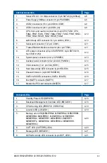

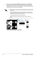
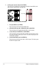


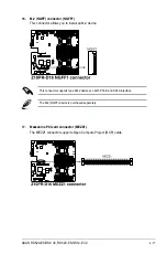


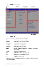

Chapter 4: Motherboard Information
4-14
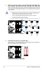
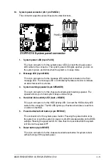
11. Auxiliary panel connector (20-2 pin AUX_PANEL1)
This connector is for additional front panel features including front panel SMB, locator
LED and switch, chassis intrusion, and LAN LEDs.
1. Front panel SMB (10-2 pin FPSMB)
These connectors are for the front panel SMBus cable.
2. LAN activity LED (2-pin LAN1_LINKACTLED, LAN2_LINKACTLED)
These connectors are for Gigabit LAN activity LEDs on the front panel.
3. Locator LED (2-pin LOCATORLED1, LOCATORLED2)
These connectors are for the locator LED1 and LED2 on the front panel. Connect
the Locator LED cables to these 2-pin connector. The LEDs will light up when the
Locator button is pressed.
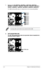
4. Locator Button/Switch (2-pin LOCATORBTN#)
These connectors are for the locator button on the front panel. This button queries
the state of the system locator.
Содержание RS520-E8-RS12-EV2
Страница 1: ...Server User Guide RS520 E8 RS8 V2 RS520 E8 RS12 EV2 ...
Страница 12: ...xii ...
Страница 56: ...Chapter 2 Hardware Information 2 32 ...
Страница 82: ...Chapter 4 Motherboard Information 4 22 ...
Страница 106: ...5 24 Chapter 5 BIOS Setup 5 5 IntelRCSetup menu ...
Страница 136: ...5 54 Chapter 5 BIOS Setup ...
Страница 174: ...6 38 Chapter 6 RAID Configuration ...
Страница 202: ...7 28 Chapter 7 Driver Installation ...
Страница 203: ...A Contact Information Appendices ...


