Asus PRIME TRX40-PRO Скачать руководство пользователя страница 70

3-8

Chapter 3: BIOS Setup

Chapter 3

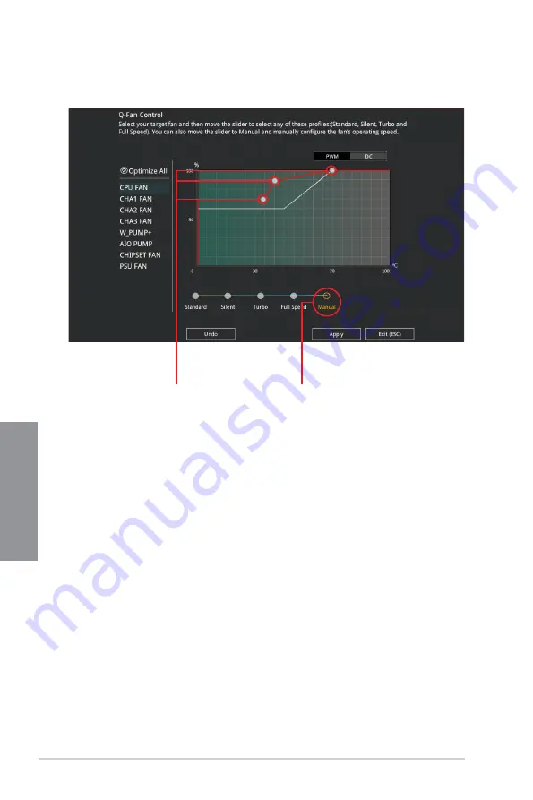
Configuring fans manually

Select 

Manual

 from the list of profiles to manually configure your fans’ operating speed.

To configure your fans:

1. 

Select the fan that you want to configure and to view its current status.

2. 

Click and drag the speed points to adjust the fans’ operating speed.

3. 

Click 

Apply

 to save the changes then click 

Exit (ESC)

.

Speed points

Select to manually 

configure your fans

Содержание PRIME TRX40-PRO

Страница 1: ...Motherboard PRIME TRX40 PRO ...

Страница 2: ...ir respective companies and are used only for identification or explanation and to the owners benefit without intent to infringe Offer to Provide Source Code of Certain Software This product contains copyrighted software that is licensed under the General Public License GPL under the Lesser General Public License Version LGPL and or other Free Open Source Software Licenses Such software in this pr...

Страница 3: ... Installation 2 1 Building your PC system 2 1 2 1 1 CPU installation 2 1 2 1 2 Cooling system installation 2 4 2 1 3 Motherboard installation 2 5 2 1 4 DIMM installation 2 6 2 1 5 ATX power connection 2 7 2 1 6 SATA device connection 2 8 2 1 7 Front I O connector 2 9 2 1 8 Expansion card installation 2 10 2 1 9 M 2 installation 2 11 2 1 10 Fan bracket installation 2 14 2 1 11 M 2 Wi Fi module and ...

Страница 4: ...n 3 14 3 6 6 NVMe Configuration 3 14 3 6 7 SATA Configuration 3 14 3 6 8 Onboard Devices Configuration 3 15 3 6 9 APM Configuration 3 17 3 6 10 Network Stack Configuration 3 17 3 6 11 AMD CBS 3 17 3 6 12 AMD PBS 3 17 3 6 13 AMD Overclocking 3 17 3 7 Monitor menu 3 18 3 8 Boot menu 3 18 3 9 Tool menu 3 20 3 9 1 ASUS EZ Flash 3 Utility 3 20 3 9 2 Secure Erase 3 21 3 9 3 ASUS User Profile 3 22 3 9 4 ...

Страница 5: ...v Chapter 4 RAID Support 4 1 AMD RAID Array configurations 4 1 4 1 1 RAID definitions 4 1 Appendix Q Code table A 1 Notices A 5 ASUS contact information A 10 ...

Страница 6: ...your area If you are not sure about the voltage of the electrical outlet you are using contact your local power company If the power supply is broken do not try to fix it by yourself Contact a qualified service technician or your retailer Operation safety Before installing the motherboard and adding devices on it carefully read all the manuals that came with the package Before using the product en...

Страница 7: ... installing system components Chapter 3 BIOS Setup This chapter tells how to change system settings through the BIOS Setup menus Detailed descriptions of the BIOS parameters are also provided Chapter 4 RAID Support This chapter describes the RAID configurations Where to find more information Refer to the following sources for additional information and for product and software updates 1 ASUS websi...

Страница 8: ...lete a task IMPORTANT Instructions that you MUST follow to complete a task NOTE Tips and additional information to help you complete a task Typography Bold text Indicates a menu or an item to select Italics Used to emphasize a word or a phrase Key Keys enclosed in the less than and greater than sign means that you must press the enclosed key Example Enter means that you must press the Enter or Ret...

Страница 9: ...ils Expansion Slots 3rd Gen AMD Ryzen Threadripper Desktop Processors 3 x PCIe 4 0 x16 Safeslots supports x16 x16 x16 mode AMD TRX40 chipset 1 x PCIe 4 0 x4 Multi GPU Support Supports NVIDIA 2 Way SLI Technology Supports AMD 2 Way CrossFireX Technology Storage 3rd Gen AMD Ryzen Threadripper Desktop Processors 2 x M 2 Socket 3 M 2_1 and M 2_2 with M key type 2242 2260 2280 22110 storage devices sup...

Страница 10: ...made audio capacitors provides warm natural and immersive sound with exceptional clarity and fidelity High quality 120dB SNR stereo playback output Line out back 108dB SNR input Line in support DTS X Ultra Supports jack detection multi streaming front panel jack retasking MIC Optical S PDIF out port at back I O USB 3rd Gen AMD Ryzen Threadripper Desktop Processors 2 x USB 3 2 Gen 2 ports 1 x Type ...

Страница 11: ... CPU performance power saving digital power control system cooling and app usages DIGI Power Control TPU EPU Fan Xpert 4 Turbo App UEFI BIOS CrashFree BIOS 3 EZ Flash 3 BIOS FlashBack Gaming Armoury Crate AURA SYNC ASUS NODE hardware control interface Turbo LAN EZ DIY Pre mounted I O Shield FlexKey Q Design ASUS Q Code ASUS Q Connector ASUS Q DIMM ASUS Q LED CPU DRAM VGA Boot Device LED ASUS Q Slo...

Страница 12: ...on World class circuit protecting power design ASUS DIGI VRM digital power design ASUS DRAM Overcurrent Protection Enhanced DRAM overcurrent protection ASUS Stainless Steel Back I O 3X corrosion resistance for greater durability AI Suite 3 Ai Charger ASUS Quiet Thermal Solution Quiet Thermal Design ASUS Fan Xpert 4 ASUS Stylish MOS M 2 heatsink chipset fan with heatsink Design Back Panel I O Ports...

Страница 13: ...or 1 x 4 Pin CPU_OPT fan connector 1 x 3 pin Chipset fan connector 3 x 4 Pin Chassis Fan connectors 1 x 2 pin Thermal sensor header 1 x 24 pin EATX Power connector 2 x 8 pin EATX 12V Power connectors 2 x Aura Addressable Gen2 headers 2 x Aura RGB headers 1 x NODE connector 1 x Front panel audio connector AAFP 1 x System panel connector with FlexKey 1 x Q Code 1 x Clear CMOS header 1 x Power on but...

Страница 14: ...le LED extension cable 1 x RGB LED extension cable 4 x SATA 6 0Gb s cables Accessories 1 x M 2 Screw package 1 x M 2 E key Screw package 1 x M 2 22110 vertical bracket 1 x FAN holder 1 x Q connector Application DVD 1 x Motherboard support DVD Documentation 1 x User guide If any of the above items is damaged or missing contact your retailer ...

Страница 15: ...er PC chassis Power supply unit AMD Socket sTRX4 CPU AMD Socket sTRX4 compatible CPU Fan DDR4 DIMM SATA hard disk drive SATA optical disc drive optional Graphics card optional The tools and components in the table above are not included in the motherboard package ...

Страница 16: ...xvi ...

Страница 17: ...cket before touching any component Before handling components use a grounded wrist strap or touch a safely grounded object or a metal object such as the power supply case to avoid damaging them due to static electricity Hold components by the edges to avoid touching the ICs on them Whenever you uninstall any component place it on a grounded antistatic pad or in the bag that came with the component...

Страница 18: ...1 2 Chapter 1 Product Introduction Chapter 1 1 2 Motherboard layout Refer to Internal connectors and Rear I O connection for more information about rear panel connectors and internal connectors ...

Страница 19: ... 1 20 7 M 2 slot 1 14 8 USB 3 2 Gen 2 connector 1 15 9 USB 3 2 Gen 1 connector 1 15 10 SATA 6Gb s connector 1 13 11 Chipset Fan connector 1 16 12 Clear RTC RAM jumper 1 10 13 System Panel connector 1 22 14 USB 2 0 connector 1 16 15 Node connector 1 18 16 Thermal Sensor connector 1 18 17 Power button 1 9 18 Q Code LED 1 11 19 Front Panel Audio connector 1 21 20 M 2 Wi Fi slot 1 14 21 LED connector ...

Страница 20: ...that all power cables are unplugged before installing the CPU Overclocking AMD processors including without limitation altering clock frequencies multipliers or memory timing voltage to operate beyond their stock specifications will void any applicable AMD product warranty even when such overclocking is enabled via AMD hardware and or software This may also void warranties offered by the system ma...

Страница 21: ...s with Dual Inline Memory Modules DIMM slots designed for DDR4 Double Data Rate 4 memory modules A DDR4 memory module is notched differently from a DDR DDR2 or DDR3 module DO NOT install a DDR DDR2 or DDR3 memory module to the DDR4 slot Recommended memory configurations ...

Страница 22: ...eration frequency is dependent on its Serial Presence Detect SPD which is the standard way of accessing information from a memory module Under the default state some memory modules for overclocking may operate at a lower frequency than the vendor marked value For system stability use a more efficient memory cooling system to support a full memory load or overclocking condition Always install the D...

Страница 23: ...PRIME TRX40 PRO 1 7 Chapter 1 1 5 Expansion slots Unplug the power cord before adding or removing expansion cards Failure to do so may cause you physical injury and damage motherboard components ...

Страница 24: ...in power plugs when running CrossFireX or SLI mode Connect a chassis fan to the chassis fan connectors when using multiple graphics cards for better thermal environment Recommended VGA configuration 3rd Gen AMD Ryzen Threadripper Desktop Processors Slot Description Single VGA SLI CFX 1 PCIe 4 0 x16_1 x16 x16 x16 2 PCIe 4 0 x16_2 x16 3 PCIe 4 0 x16_3 x16 ...

Страница 25: ...the system or put the system into sleep or soft off mode depending on the operating system settings The button also lights up when the system is plugged to a power source indicating that you should shut down the system and unplug the power cable before removing or installing any motherboard component ...

Страница 26: ...t circuit pin 1 2 with a metal object or jumper cap for about 5 10 seconds 3 Plug the power cord and turn ON the computer 4 Hold down the Del key during the boot process and enter BIOS setup to re enter data DO NOT short circuit the pins except when clearing the RTC RAM Short circuiting or placing a jumper cap will cause system boot failure If the steps above do not help remove the onboard button ...

Страница 27: ...s provide the most probable cause of an error code as a starting point for troubleshooting The actual cause may vary from case to case 2 Q Code LED The Q Code LED design provides you with a 2 digit error code that displays the system status The Q Code LEDs provide the most probable cause of an error code as a starting point for troubleshooting The actual cause may vary from case to case Please ref...

Страница 28: ... 8 pin Power Plug LED The 8 pin Power Plug LED lights up to indicate that the 8 pin power plug is not connected Ensure to connect both 8 pin power plugs Due to the CPU minimum power consumption requirement we recommend using a PSU with 850W or above ...

Страница 29: ...u installed SATA storage devices you can create a RAID 0 1 and 10 configuration through the onboard AMD TRX40 chipset These connectors are set to AHCI by default If you intend to create a SATA RAID set using these connectors set the SATA Mode Selection item in the BIOS to RAID Before creating a RAID set refer to the RAID Configuration Guide You can download the RAID Configuration Guide from the AS...

Страница 30: ... 2_3 socket supports PCIe 4 0 x4 and SATA modes vertical M Key design and type 2242 2260 2280 22110 storage devices The M 2 SSD module is purchased separately Use the bundled bracket to install a vertical M 2 SSD module to the M 2_3 socket refer to the M 2 Installation section for more details 3 M 2 Wi Fi slot The M 2 Wi Fi slot allows you to install an M 2 Wi Fi module E key type 2230 The M 2 Wi ...

Страница 31: ... up to 5 Gb s The USB 3 2 Gen 1 module is purchased separately The plugged USB 3 2 Gen 1 device may run on xHCI or EHCI mode depending on the operating system s setting 4 USB 3 2 Gen 2 connector The USB 3 2 Gen 2 connector allows you to connect a USB 3 2 Gen 2 module for additional USB 3 2 Gen 2 ports The USB 3 2 Gen 2 connector provides data transfer speeds of up to 10 Gb s The USB 3 2 Gen 2 modu...

Страница 32: ...SB 2 0 ports The USB 2 0 connector provides data transfer speeds of up to 480 MB s connection speed DO NOT connect a 1394 cable to the USB connectors Doing so will damage the motherboard The USB 2 0 module is purchased separately 7 Chipset Fan connector The Chipset Fan connector is for connecting the chipset fan on the integrated heatsink ...

Страница 33: ... the fan connectors Ensure the cable is fully inserted into the connector For water cooling kits connect the pump connector to the W_PUMP connector then connect the fan connectors to the CPU_FAN and CPU_OPT connectors Header Max Current Max Power Default Speed Shared Control CPU_FAN 1A 12W Q Fan Controlled A CPU_OPT 1A 12W Q Fan Controlled A CHA_FAN1 1A 12W Q Fan Controlled CHA_FAN2 1A 12W Q Fan C...

Страница 34: ...formation about the devices and the latest compatibility list 10 Thermal Sensor connector The Thermal Sensor connector allows you to connect a sensor to monitor the temperature of the devices and the critical components inside the motherboard Connect the thermal sensor and place it on the device or the motherboard s component to detect its temperature The thermal sensor is purchased separately ...

Страница 35: ...or remove any component ensure that the power supply is switched off or the power cord is detached from the power supply Failure to do so may cause severe damage to the motherboard peripherals or components Actual lighting and color will vary with LED strip If your LED strip does not light up check if the addressable RGB LED strip is connected in the correct orientation and the 5V connector is ali...

Страница 36: ...supply is switched off or the power cord is detached from the power supply Failure to do so may cause severe damage to the motherboard peripherals or components Actual lighting and color will vary with LED strip If your LED strip does not light up check if the RGB LED extension cable and the RGB LED strip is connected in the correct orientation and the 12V connector is aligned with the 12V header ...

Страница 37: ...tor The front panel audio connector is for a chassis mounted front panel audio I O module that supports HD Audio Connect one end of the front panel audio I O module cable to this connector We recommend that you connect a high definition front panel audio module to this connector to avail of the motherboard s high definition audio capability ...

Страница 38: ... read from or written to the storage device or storage device add on card System Warning Speaker connector SPEAKER The 4 pin connector allows you to connect the chassis mounted system warning speaker The speaker allows you to hear system beeps and warnings Power Button Soft off Button connector PWRBTN The 3 1 pin connector allows you to connect the system power button Press the power button to pow...

Страница 39: ...a power supply The power supply plugs are designed to fit in only one orientation find the proper orientation and push down firmly until the power supply plugs are fully inserted Ensure to connect both 8 pin power plugs Due to the CPU minimum power consumption requirement we recommend using a PSU with 850W or above ...

Страница 40: ...1 24 Chapter 1 Product Introduction Chapter 1 ...

Страница 41: ...ors Ensure you use a CPU designed for the Socket sTRX4 The CPU fits in only one correct orientation DO NOT force the CPU into the socket to prevent bending the connectors on the socket and damaging the CPU External cap Load plate Rail frame C D 1 2 3 A B Load plate Use the bundled Torx screwdriver to remove the load plate screws in sequence 3 2 1 then lift the load plate Use your fingers to pull u...

Страница 42: ...B A 1 2 3 B B C A 1 2 3 A B PnP cap Carrier frame with CPU Slide the carrier frame with CPU into the rail frame until you hear a click sound then remove the PnP cap C D 1 2 3 B B C A A B Carrier frame with CPU Gently press down the rail frame until it latches to the socket housing then press down the load plate ...

Страница 43: ...screws are Torx T20 models A torque value of 12 inch lbf is recommended A B C D B B C A 1 2 3 Drive the three screws slightly into the holes in sequence 1 2 3 just enough to attach the load plate to the socket When the three screws are attached tighten them in sequence 1 2 3 to completely secure the load plate Then apply the Thermal Interface Material to the CPU ...

Страница 44: ...2 4 Chapter 2 Basic Installation Chapter 2 2 1 2 Cooling system installation To install the CPU heatsink and fan assembly ...

Страница 45: ...g that its rear I O ports are aligned to the chassis rear I O panel 2 1 3 Motherboard installation DO NOT over tighten the screws Doing so can damage the motherboard Ensure that the space above the installed motherboard at least 8cm to prevent the MOS heatsink from interfering with the radiator or chassis fans We recommend using an E ATX chassis when installing this motherboard ...

Страница 46: ...2 6 Chapter 2 Basic Installation Chapter 2 2 1 4 DIMM installation To remove a DIMM ...

Страница 47: ...PRIME TRX40 PRO 2 7 Chapter 2 2 1 5 ATX power connection AND Ensure to connect the two 8 pin power plugs ...

Страница 48: ...2 8 Chapter 2 Basic Installation Chapter 2 2 1 6 SATA device connection OR ...

Страница 49: ...nstall ASUS Q Connector This connector will only fit in one orientation Push the connector until it clicks into place USB 2 0 AAFP To install USB 2 0 connector To install front panel audio connector USB 3 2 Gen 1 To install USB 3 2 Gen 1 connector To install system speaker connector USB 3 2 Gen 2 ...

Страница 50: ...2 10 Chapter 2 Basic Installation Chapter 2 2 1 8 Expansion card installation To install PCIe x16 cards To install PCIe x4 cards ...

Страница 51: ...PRIME TRX40 PRO 2 11 Chapter 2 2 1 9 M 2 installation Supported M 2 type varies per motherboard For M 2_1 and M 2_2 Type 2242 2260 2280 M 2 ...

Страница 52: ...2 12 Chapter 2 Basic Installation Chapter 2 For M 2_1 and M 2_2 Type 22110 M 2 ...

Страница 53: ...PRIME TRX40 PRO 2 13 Chapter 2 For M 2_3 Type 2242 2260 2280 22110 M 2 ...

Страница 54: ...an bracket installation To install the MOS FAN bracket and fan When using high performance settings whilst overclocking ensure to install the MOS FAN bracket for additional fan s You may install 12V 1A 12W 40mm x 40mm fans The fan is purchased separately ...

Страница 55: ... 2x2 dual band Wi Fi antenna is securely installed to the Wi Fi ports Ensure that the antenna is at least 20 cm away from all persons The illustration to the left is for reference only The I O port layout may vary with models but the Wi Fi antenna installation procedure is the same for all models The M 2 Wi Fi module is purchased separately ...

Страница 56: ... BIOS file for a BIOS FlashBack compatible motherboard 4 Shut down your computer 5 Press the BIOS FlashBack button for three seconds until the BIOS FlashBack LED blinks three times indicating that the BIOS FlashBack function is enabled BIOS FlashBack button BIOS FlashBack port 6 Wait until the light goes out indicating that the BIOS updating process is completed For more BIOS update utilities in B...

Страница 57: ...xt page for LAN port LEDs and audio port definitions Rear panel connectors 1 USB 3 2 Gen 1 ports E1234 2 BIOS FlashBack button 3 USB 3 2 Gen 1 ports 56 4 USB 3 2 Gen 2 port 1 5 LAN RJ 45 port 6 USB 3 2 Gen 2 Type C port C2 7 USB 3 2 Gen 2 ports 34 Lower port supports BIOS FlashBack function 8 Optical S PDIF OUT port 9 Audio I O ports ...

Страница 58: ...peaker Out Red Mic In Mic In Mic In Mic In Orange Center Sub woofer Center Sub woofer White Rear Speaker Out Rear Speaker Out Rear Speaker Out LAN ports LED indications Activity Link LED Speed LED Status Description Status Description OFF No link OFF 10 Mbps connection ORANGE Linked ORANGE 100 Mbps connection ORANGE Blinking Data activity GREEN 1 Gbps connection ORANGE Blinking then Steady Ready t...

Страница 59: ...PRIME TRX40 PRO 2 19 Chapter 2 2 3 2 Audio I O connections Audio I O ports Connect to Headphone and Mic Connect to Stereo Speakers Connect to 2 channel Speakers ...

Страница 60: ...2 20 Chapter 2 Basic Installation Chapter 2 Connect to 4 channel Speakers Connect to 6 channel Speakers Connect to 8 Speakers ...

Страница 61: ...tests POST While the tests are running the BIOS beeps refer to the BIOS beep codes table or additional messages appear on the screen If you do not see anything within 30 seconds from the time you turned on the power the system may have failed a power on test Check the jumper settings and connections or call your retailer for assistance BIOS Beep Description One short beep VGA detected Quick boot s...

Страница 62: ...2 22 Chapter 2 Basic Installation Chapter 2 ...

Страница 63: ...cking settings advanced power management and boot device configuration that are needed for system startup in the motherboard CMOS In normal circumstances the default BIOS settings apply to most conditions to ensure optimal performance DO NOT change the default BIOS settings except in the following circumstances An error message appears on the screen during the system bootup and requests you to run...

Страница 64: ...not support the Bluetooth devices Please visit ASUS website for the detailed BIOS content manual BIOS menu screen The BIOS Setup program can be used under two modes EZ Mode and Advanced Mode You can change modes from Setup Mode in Boot menu or by pressing the F7 hotkey 3 2 BIOS setup program Use the BIOS Setup to update the BIOS or configure its parameters The BIOS screen include navigation keys a...

Страница 65: ...s for the detailed configurations The default screen for entering the BIOS setup program can be changed Refer to the Setup Mode item in section Boot menu for details Menu items General help Menu bar Language Qfan Control F6 MyFavorite F3 AURA ON OFF F4 Search F9 Scroll bar Pop up Menu Configuration fields Last modified settings Go back to EZ Mode Displays a quick overview of the system status and ...

Страница 66: ...Advanced Monitor Boot Tool and Exit on the menu bar have their respective menu items Submenu items A greater than sign before each item on any menu screen means that the item has a submenu To display the submenu select the item and press Enter Language This button above the menu bar contains the languages that you can select for your BIOS Click this button to select the language that you want to d...

Страница 67: ...avigation keys to select items in the menu and change the settings Scroll bar A scroll bar appears on the right side of a menu screen when there are items that do not fit on the screen Press the Up Down arrow keys or Page Up Page Down keys to display the other items on the screen General help At the bottom of the menu screen is a brief description of the selected item Use F12 key to capture the BI...

Страница 68: ...de F7 or press the F7 hotkey The boot device options vary depending on the devices you installed to the system Selects the display language of the BIOS setup program Displays a quick overview of the system status Displays the system properties of the selected mode Click or to switch modes Loads optimized default settings Displays the CPU Fan s speed Click the button to manually tune the fans Saves...

Страница 69: ...onfigure the operating speed of your CPU and chassis fans Click to select a fan to be configured Click to activate PWM Mode Click to undo the changes Click to apply the fan setting Click to go back to main menu Select a profile to apply to your fans Click to activate DC Mode Select to manually configure your fans ...

Страница 70: ...ly configure your fans operating speed To configure your fans 1 Select the fan that you want to configure and to view its current status 2 Click and drag the speed points to adjust the fans operating speed 3 Click Apply to save the changes then click Exit ESC Speed points Select to manually configure your fans ...

Страница 71: ... Favorites is your personal space where you can easily save and access your favorite BIOS items My Favorites comes with several performance power saving and fast boot related items by default You can personalize this screen by adding or removing items ...

Страница 72: ...enu that you want to save as favorite from the submenu panel and click or press Enter on your keyboard You cannot add the following items to My Favorite items Items with submenu options User managed items such as language and boot order Configuration items such as Memory SPD Information system time and date 4 Click Exit ESC or press Esc key to close Setup Tree Map screen 5 Go to My Favorites menu ...

Страница 73: ...ing related items Be cautious when changing the settings of the Ai Tweaker menu items Incorrect field values can cause the system to malfunction The configuration options for this section vary depending on the CPU and DIMM model you installed on the motherboard Ai Overclock Tuner Allows you to select the CPU overclocking options to achieve the desired CPU internal frequency Auto Loads the optimal ...

Страница 74: ...ow you to change the settings for the CPU and other system devices Be cautious when changing the settings of the Advanced menu items Incorrect field values can cause the system to malfunction 3 6 1 AMD fTPM configuration The items in this menu show the AMD fTPM configuration options AMD CPU fTPM This item allows you to enable or disable AMD CPU fTPM Configuration options Enable Disable When AMD CP...

Страница 75: ...gs Allows you to configure PCI PCI X and PCI Express Settings Above 4G Decoding Allows you to enable or disable 64 bit capable devices to be decoded in above 4G address space It only works if the system supports 64 bit PCI decoding Configuration options On Off SR IOV Support This option enables or disables Single Root IO Virtualization Support if the system has SRIOV capable PCIe devices Configura...

Страница 76: ...rating systems without an XHCI hand off feature Disabled Disables the XHCI Hand off support USB Single Port Control This item allows you to enable or disable the individual USB ports Refer to section Motherboard layout for the location of the USB ports 3 6 5 HDD SSD SMART Information This menu displays the SMART information of the connected devices 3 6 6 NVMe Configuration You may view the NVMe co...

Страница 77: ...able the NVMe RAID mode Configuration options Disabled Enabled SMART Self Test S M A R T Self Monitoring Analysis and Reporting Technology is a monitoring system that shows a warning message during POST Power on Self Test when an error occurs in the hard disks Configuration options On Off SATA6G_1 Gray SATA6G_8 Gray SATA6G_1 Gray SATA6G_8 Gray This item allows you to enable or disable the selected...

Страница 78: ...dth X16 Mode The PCIe x16_3 slot runs at x16 mode PCIe RAID Mode The four PCIe x16 slots run at x4 x4 x4 x4 mode which allows you to create a RAID array for up to 4 PCIe devices Use PCIe RAID Mode when installing the Hyper M 2 x16 card or other M 2 adapter cards Installing other devices when using PCIe RAID Mode may cause your PC to fail to boot up HD Audio Controller This item allows you to use t...

Страница 79: ... Ready This item allows you to switch off some power at S4 S5 or S5 to get the system ready for ErP requirement When set to Enabled all other PME options are switched off Configuration options Disabled Enable S4 S5 Enable S5 Power On By PCI E This item allows you to enable or disable the Wake on LAN function of the onboard LAN controller or other installed PCI E LAN cards Configuration options Dis...

Страница 80: ...feature Auto Detects the type of AIO pump installed and automatically switches the control modes DC mode Enable the AIO Pump control in DC mode for 3 pin chassis fan PWM mode Enable the AIO Pump control in PWM mode for 4 pin chassis fan 3 8 Boot menu The Boot menu items allow you to change the system boot options Boot Configuration Fast Boot Disabled Allows your system to go back to its normal boo...

Страница 81: ...e following items appear only when Launch CSM is set to Enabled Boot Device Control This item allows you to select the type of devices that you want to boot Configuration options UEFI and Legacy OPROM Legacy OPROM only UEFI only Boot from Network Devices This item allows you to select the type of network devices that you want to launch Configuration options Ignore Legacy only UEFI driver first Boo...

Страница 82: ... devices installed in the system Click an item to start booting from the selected device AMI Native NVMe Driver Support This item allows you to enable or disable all NVMe device native OpROM Configuration options On Off 3 9 Tool menu The Tool menu items allow you to configure options for special functions Select an item then press Enter to display the submenu Setup Animator This item allows you to...

Страница 83: ...ending on its size Do not turn off the system during the process Secure Erase is only supported on AMD SATA port For more information about AMD SATA ports refer to section Motherboard layout of this manual Status definition Frozen The frozen state is the result of a BIOS protective measure The BIOS guards drives that do not have password protection by freezing them prior to booting If the drive is...

Страница 84: ...le Name This item allows you to key in a profile name Save to Profile This item allows you to save the current BIOS settings to the BIOS Flash and create a profile Key in a profile number from one to eight press Enter and then select Yes Load Save Profile from to USB Drive This item allows you to load or save profile from your USB drive load and save profile to your USB drive 3 9 4 ASUS SPD Inform...

Страница 85: ...nges Reset Once you are finished making your selections choose this option from the Exit menu to ensure the values you selected are saved When you select this option or if you press F10 a confirmation window appears Select OK to save changes and exit Discard Changes Exit This option allows you to exit the Setup program without saving your changes When you select this option or if you press Esc a c...

Страница 86: ...m to download the latest BIOS file for this motherboard The following utilities allow you to manage and update the motherboard BIOS setup program 1 EZ Update Updates the BIOS in Windows environment 2 ASUS EZ Flash 3 Updates the BIOS using a USB flash drive 3 ASUS CrashFree BIOS 3 Restores the BIOS using the motherboard support USB drive when the BIOS file fails or gets corrupted 3 11 1 EZ Update T...

Страница 87: ... arrow keys to find the USB flash disk that contains the latest BIOS and then press Enter 6 Press Tab to switch to the Folder Info field 7 Press the Up Down arrow keys to find the BIOS file and then press Enter to perform the BIOS update process Reboot the system when the update process is done This function can support devices such as a USB flash disk with FAT 32 16 format and single partition on...

Страница 88: ...ile download the file at https www asus com support and save it to a USB flash drive Recovering the BIOS To recover the BIOS 1 Turn on the system 2 Insert the motherboard support DVD support USB drive or a USB flash drive containing the BIOS file to the USB port 3 The utility automatically checks the devices for the BIOS file When found the utility reads the BIOS file and enters ASUS EZ Flash 3 au...

Страница 89: ...to create RAIDABLE arrays may vary per system RAID 0 Data striping optimizes two identical hard disk drives to read and write data in parallel interleaved stacks Two hard disks perform the same work as a single drive but at a sustained data transfer rate double that of a single disk alone thus improving data access and storage Use of two new identical hard disk drives is required for this setup RA...

Страница 90: ...4 2 Chapter 4 RAID Support Chapter 4 ...

Страница 91: ...1 14 Pre memory CPU initialization is started 15 18 Pre memory System Agent initialization is started 19 1C Pre memory PCH initialization is started 2B 2F Memory initialization 30 Reserved for ASL see ASL Status Codes section below 31 Memory Installed 32 36 CPU post memory initialization 37 3A Post Memory System Agent initialization is started 3B 3E Post Memory PCH initialization is started 4F DXE...

Страница 92: ... F5 F7 Reserved for future AMI progress codes F8 Recovery PPI is not available F9 Recovery capsule is not found FA Invalid recovery capsule FB FF Reserved for future AMI error codes 60 DXE Core is started 61 NVRAM initialization 62 Installation of the PCH Runtime Services 63 67 CPU DXE initialization is started 68 PCI host bridge initialization 69 System Agent DXE initialization is started 6A Syst...

Страница 93: ...USB Reset 9C USB Detect 9D USB Enable 9E 9F Reserved for future AMI codes A0 IDE initialization is started A1 IDE Reset A2 IDE Detect A3 IDE Enable A4 SCSI initialization is started A5 SCSI Reset A6 SCSI Detect A7 SCSI Enable A8 Setup Verifying Password A9 Start of Setup AA Reserved for ASL see ASL Status Codes section below AB Setup Input Wait AC Reserved for ASL see ASL Status Codes section belo...

Страница 94: ...Image returned error DA Boot Option is failed StartImage returned error DB Flash update is failed DC Reset protocol is not available Q Code table ACPI ASL Checkpoints under OS Code Description 0x01 System is entering S1 sleep state 0x02 System is entering S2 sleep state 0x03 System is entering S3 sleep state 0x04 System is entering S4 sleep state 0x05 System is entering S5 sleep state 0x10 System ...

Страница 95: ...gainst harmful interference in a residential installation This equipment generates uses and can radiate radio frequency energy and if not installed and used in accordance with the instructions may cause harmful interference to radio communications However there is no guarantee that interference will not occur in a particular installation If this equipment does cause harmful interference to radio o...

Страница 96: ...ing interference that may cause undesired operation of the device CAN ICES 3 B NMB 3 B Déclaration de conformité de Innovation Sciences et Développement économique Canada ISED Le présent appareil est conforme aux CNR d Innovation Sciences et Développement économique Canada applicables aux appareils radio exempts de licence L exploitation est autorisée aux deux conditions suivantes 1 l appareil ne ...

Страница 97: ...iance htm for information disclosure based on regulation requirements ASUS is complied with EU REACH and Article 33 Complying with the REACH Registration Evaluation Authorisation and Restriction of Chemicals regulatory framework we published the chemical substances in our products at ASUS REACH website at http csr asus com english REACH htm EU RoHS This product complies with the EU RoHS Directive ...

Страница 98: ...ions DO NOT throw the motherboard in municipal waste This product has been designed to enable proper reuse of parts and recycling This symbol of the crossed out wheeled bin indicates that the product electrical and electronic equipment should not be placed in municipal waste Check local regulations for disposal of electronic products DO NOT throw the mercury containing button cell battery in munic...

Страница 99: ...иям и другим соответствующим условиям соответствующих директив Подробную информацию пожалуйста смотрите на www asus com support Български С настоящото ASUSTeK Computer Inc декларира че това устройство е в съответствие със съществените изисквания и другите приложими постановления на свързаните директиви Пълният текст на декларацията за съответствие на ЕС е достъпна на адрес www asus com support Hrv...

Страница 100: ...to Rd Fremont CA 94538 USA Telephone 1 510 739 3777 Fax 1 510 608 4555 Web site http www asus com us Technical Support Support fax 1 812 284 0883 Telephone 1 812 282 2787 Online support https www asus com support Product ContactUs Services questionform lang en us ASUS COMPUTER GmbH Germany and Austria Address Harkort Str 21 23 40880 Ratingen Germany Fax 49 2102 959931 Web site http www asus com de...

Отзывы: