ASUS PRIME Q370M-C
1-3
Intel
®
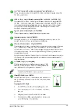
Q370 Serial ATA 6.0Gb/s connectors (7-pin SATA6G_1~6)
These connectors connect to Serial ATA 6.0 Gb/s hard disk drives via Serial ATA
6.0 Gb/s signal cables.
USB 3.1 Gen 1 (up to 5Gbps) connectors (20-1 pin U31G1_56; U31G1_78)
Connect a USB 3.1 Gen 1 module to any of these connectors for additional USB
3.1 Gen 1 front or rear panel ports. These connectors comply with USB 3.1 Gen
1 specifications and provide faster data transfer speeds of up to 5 Gbps, faster
charging time for USB-chargeable devices, optimized power efficiency, and
backward compatibility with USB 2.0.
System panel connector (10-1 pin F_PANEL)
This connector supports several chassis-mounted functions.
Speaker connector (4-pin SPEAKER)
The 4-pin connector is for the chassis-mounted system warning speaker. The
speaker allows you to hear system beeps and warnings.
Chassis intrusion header (4-1 pin CHASSIS)
This header is for a chassis-mounted intrusion detection sensor or switch. Connect
one end of the chassis intrusion sensor or switch cable to this connector. The
chassis intrusion sensor or switch sends a high-level signal to this connector when
a chassis component is removed or replaced. The signal is then generated as a
chassis intrusion event.
By default, the pin labeled “Chassis Signal” and “Ground” are shorted with a jumper
cap. Remove the jumper caps only when you intend to use the chassis intrusion
detection feature.
Intel
®
ME jumper (3-pin DIS_ME)
This jumper allows you to enable or disable the Intel
®
ME
function. Set this jumper to pins 1-2 to enable (default) the
Intel
®
ME function and to pins 2-3 to disable it.
2
2 3
Normal
(Default)
Disable ME
DIS_ME
1
Disable the Intel
®
ME function before updating it.
Clear RTC RAM (2-pin CLRTC)
This header allows you to clear the CMOS RTC RAM data of
the system setup information such as date, time, and system
passwords.
To erase the RTC RAM:
1.
Turn OFF the computer and unplug the power cord.
2.
Use a metal object such as a screwdriver to short the
two pins.
3.
Plug the power cord and turn ON the computer.
4.
Hold down the <
Del
> key during the boot process and
enter BIOS setup to re-enter data.
CLRTC
+3V_BAT GND
PIN 1


