


ASUS P7H55-M PRO
2-3
Chapter 2
2.2.2
Layout contents
Connectors/Jumpers/Slots
Page
1.
ATX power connectors (24-pin EATXPWR, 8-pin EATX12V)
2-33
2.
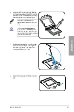
LGA1156 CPU Socket
2-5
3.
CPU, chassis, and power fan connectors (4-pin CPU_FAN,
4-pin CHA_FAN1, 3-pin PWR_FAN)
2-31
4.
DDR3 DIMM slots
2-10
5.
Intel
®
H55 Serial ATA connectors (7-pin SATA 1-6)
2-29
6.
IDE connector (40-1 pin PRI_EIDE)
2-28
7.
System panel connector (20-8 pin PANEL)
2-34
8.
Serial port connector (10-1 pin COM1)
2-30
9.
USB connectors (10-1 pin USB78, USB910, USB1112)
2-30
10.
Clear RTC RAM (3-pin CLRTC)
2-22
11.
Digital audio connector (4-1 pin SPDIF_OUT)
2-32
12.
Front panel audio connector (10-1 pin AAFP)
2-32
13.
Standby power LED
2-1
Содержание P7H55 DVI
Страница 1: ...Motherboard P7H55 M PRO ...
Страница 14: ...xiv ...
Страница 20: ...1 6 Chapter 1 Product Introduction Chapter 1 ...
Страница 56: ...2 36 Chapter 2 Hardware information Chapter 2 ...
Страница 96: ...3 40 Chapter 3 BIOS setup Chapter 3 ...
Страница 108: ...4 12 Chapter 4 Software support Chapter 4 ...