


2-14
Chapter 2: Hardware information
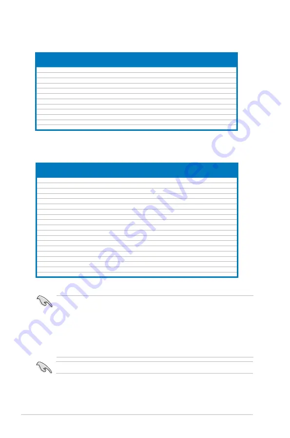
P5Q3 Deluxe WiFi-AP@n Motherboard
Qualified Vendors Lists (QVL) DDR3-1333MHz capability
Size
Vendor
Chip No.
Chip Brand SS/DS Part No.
DIMM socket support
(Optional)
A*
B*
C*
1024MB
CORSAIR
Heat-Sink Package
N/A
DS
CM3X1024-1333C9DHX
•
•
•
1024MB
KINGMAX
J1108BASE-DJ-E
ELPIDA
SS
FLFD45F-B8EE9
•
•
•
1024MB
Kingston
IDSH51-03A1F1C-13G
QIMONDA
DS
KVR1333D3N8/1G
•
•
•
1024MB
Kingston
J5308BASE-DG-E
ELPIDA
DS
KVR1333D3N8/1G
•
•
1024MB
MICRON
Z9HWR
MICRON
SS
MT8JTF12864AY-1G4BYES
•
•
•
2048MB MICRON
Z9HWR
MICRON
DS
MT16JTF25664AY-1G4BYES
•
•
•
1024MB
OCZ
Heat-Sink Package
N/A
DS
OCZ3P13332GK
•
•
1024MB
SAMSUNG
K4B1G0846C-ZCF8
SAMSUNG SS
M378B2873CZ0-CG9
•
1024MB
SAMSUNG
K4B1G0846C-ZCH9
SAMSUNG SS
M378B2873CZ0-CH9
•
•
•
2048MB
SAMSUNG
K4B1G0846D
SAMSUNG DS
M378B5673DZ1-CH9
•
1024MB
Patriot
Heat-Sink Package
Patriot
SS
PDC32G1333LLK
•
•
•
1024MB
PNY
IDSH51-03A1F1C-10F
QIMONDA
DS
89000632-H-PH0
•
•
•
Visit the ASUS website for the latest QVL.
Side(s): SS - Single-sided DS - Double-sided
DIMM support:
•
A*:
Supports one module inserted into either slot as Single-channel
memory configuration.
•
B*:
Supports one pair of modules inserted into either the orange slots or
the black slots as one pair of Dual-channel memory configuration.
•
C*:
Supports four modules inserted into both the orange slots and the
black slots as two pairs of Dual-channel memory configuration.
P5Q3 Deluxe WiFi-AP@n Motherboard
Qualified Vendors Lists (QVL) DDR3-1066MHz capability
Size
Vendor
Chip No.
Chip Brand SS/DS Part No.
DIMM socket support
(Optional)
A*
B*
C*
1024MB
A-DATA
J5308BASE-AE-E
ELPIDA
DS
M3OEL3G3I4130A1B5Z
•
•
•
1024MB
CORSAIR
Heat-Sink Package
N/A
DS
CM3X1024-1066C7
•
•
•
1024MB
Crucial
Z9HWQ
MICRON
SS
CT12864BA1067.8SFB
•
•
•
1024MB
ELPIDA
J5308BASE-AC-E
ELPIDA
DS
EBJ11UD8BAFA-AG-E
•
•
•
1024MB
Hynix
HY5TQ1G831ZNFP-G7
HYNIX
SS
HYMT112U64ZNF8-G7
•
•
•
2048MB
Hynix
HY5TQ1G831ZNFP-G7
HYNIX
DS
HYMT125U64ZNF8-G7
•
•
•
1024MB
Kingston
J5308BASE-AC-E
ELPIDA
DS
KVR1066D3N7/1G
•
•
•
2048MB
Kingston
K4B1G0846C-ZCF8
N/A
DS
KVR1066D3N7/2G
•
•
•
1024MB
MICRON
7VD22
MICRON
SS
MT8JTF12864AY-1G1D1
•
•
•
2048MB
MICRON
7VD22
MICRON
DS
MT16JTF25664AY-1G1D1
•
•
•
1024MB
Qimonda
IDSH51-03A1F1C-10F
QIMONDA
DS
IMSH1GU13A1F1C-10F
•
•
•
1024MB
SAMSUNG
K4B1G0846C-ZCF8
SAMSUNG SS
M378B2873CZ0-CF8
•
•
•
1024MB
SAMSUNG
K4B1G0846C-ZCG8
SAMSUNG SS
M378B2873CZ0-CG8
•
•
•
1024MB
SAMSUNG
K4B1G0846C-ZCF8
SAMSUNG SS
M391B2873CZ0-CF8
•
•
•
2048MB
SAMSUNG
K4B1G0846C-ZCF8
SAMSUNG DS
M378B5673CZ0-CF8
•
•
•
1024MB
Aeneon
AEH93R10F
AENEON
DS
AEH760UD00-10FA98X
•
•
•
1024MB
PNY
IDSH51-03A1F1C-10F
QIMONDA
DS
64A0TEHHJ8G17BWJ-T
•
•
•
1024MB
Team
T3D1288HT-13
N/A
SS
N/A
•
•
•
1024MB
WINTEC
IDSH51-03A1F1C-10F
QIMONDA
DS
3DU3191A-10
•
•
•
Содержание P5Q3 Deluxe/WiFi-AP@n
Страница 1: ...Motherboard P5Q3 Deluxe WiFi AP n ...
Страница 16: ...xvi ...
Страница 18: ...ASUS P5Q3 Deluxe WiFi AP n Chapter summary 1 1 1 Welcome 1 1 1 2 Package contents 1 1 1 3 Special features 1 2 ...
Страница 185: ...A CPU features The Appendix describes the CPU features and technologies that the motherboard supports ...
Страница 190: ...A 4 Appendix CPU features ...


