2 - 2 6
2 - 2 6
2 - 2 6
2 - 2 6
2 - 2 6
C h a p t e r 2 : H a r d w a r e i n f o r m a t i o n
C h a p t e r 2 : H a r d w a r e i n f o r m a t i o n
C h a p t e r 2 : H a r d w a r e i n f o r m a t i o n
C h a p t e r 2 : H a r d w a r e i n f o r m a t i o n
C h a p t e r 2 : H a r d w a r e i n f o r m a t i o n
4 .
4 .
4 .
4 .
4 .
S e r i a l A T A c o n n e c t o r s
S e r i a l A T A c o n n e c t o r s
S e r i a l A T A c o n n e c t o r s
S e r i a l A T A c o n n e c t o r s
S e r i a l A T A c o n n e c t o r s
( 7 - p i n S A T A 1 , S A T A 2 , S A T A 3 , S A T A 4 )
( 7 - p i n S A T A 1 , S A T A 2 , S A T A 3 , S A T A 4 )
( 7 - p i n S A T A 1 , S A T A 2 , S A T A 3 , S A T A 4 )
( 7 - p i n S A T A 1 , S A T A 2 , S A T A 3 , S A T A 4 )
( 7 - p i n S A T A 1 , S A T A 2 , S A T A 3 , S A T A 4 )
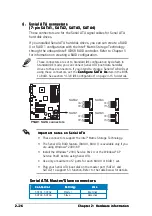
These connectors are for the Serial ATA signal cables for Serial ATA
hard disk drives.
If you installed Serial ATA hard disk drives, you can can create a RAID
0 or RAID 1 configuration with the Intel
®
Matrix Storage Technology
through the onboard Intel
®
ICH6R RAID controller. Refer to Chapter 5
for information on creating a RAID configuration.
I m p o r t a n t n o t e s o n S e r i a l A T A
I m p o r t a n t n o t e s o n S e r i a l A T A
I m p o r t a n t n o t e s o n S e r i a l A T A
I m p o r t a n t n o t e s o n S e r i a l A T A
I m p o r t a n t n o t e s o n S e r i a l A T A
•
These connectors support the Intel
®
Matrix Storage Technology.
•
The Serial ATA RAID feature (RAID 0, RAID 1) is available only if you
are using Windows
®
2000/XP.
•
Install the Windows
®
2000 Service Pack 4 or the Windows
®
XP
Service Pack1 before using Serial ATA.
•
Use only a maximum of 2 ports for each RAID 0 or RAID 1 set.
•
Plug your Serial ATA boot disk on the master port (SATA1 and
SATA2) to support S3 function. Refer to the table below for details.
Serial ATA Master/Slave connectors
Serial ATA Master/Slave connectors
Serial ATA Master/Slave connectors
Serial ATA Master/Slave connectors
Serial ATA Master/Slave connectors
P5GD1
P5GD1 SATA connectors
SATA1
SATA4
SATA3
SATA2
GND
RSATA_TXP1
RSATA_TXN1
GND
RSATA_RXP1
RSATA_RXN1
GND
GND
RSATA_TXP2
RSATA_TXN2
GND
RSATA_RXP2
RSATA_RXN2
GND
GND
RSATA_TXP4
RSATA_TXN4
GND
RSATA_RXP4
RSATA_RXN4
GND
GND
RSATA_TXP3
RSATA_TXN3
GND
RSATA_RXP3
RSATA_RXN3
GND
These connectors are set to Standard IDE configuration by default. In
Standard IDE mode, you can connect Serial ATA boot/data hard disk
drives to these connectors. If you intend to create a Serial ATA RAID set
using these connectors, set the C o n f i g u r e S A T A A s
C o n f i g u r e S A T A A s
C o n f i g u r e S A T A A s
C o n f i g u r e S A T A A s
C o n f i g u r e S A T A A s item in the BIOS
to RAID. See section “4.3.6 IDE Configuration” on page 4-15 for details.
C o n n e c t o r
C o n n e c t o r
C o n n e c t o r
C o n n e c t o r
C o n n e c t o r
S e t t i n g
S e t t i n g
S e t t i n g
S e t t i n g
S e t t i n g
U s e
U s e
U s e
U s e
U s e
SATA1, SATA2
Master
Boot disk
SATA3, SATA4
Slave
Data disk

