background image

2-10

Chapter 2: Hardware information

2.3.3 

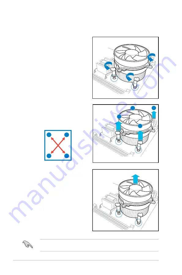
Uninstalling the CPU heatsink and fan

To uninstall the CPU heatsink and fan:
1.   Disconnect the CPU fan cable from 

the connector on the motherboard.

2.  Rotate each fastener 

counterclockwise.

3.  Pull up two fasteners at a time in 

a diagonal sequence to disengage 

the heatsink and fan assembly 

from the motherboard.

B

B

A

A

A

A

B

B

4.  Carefully remove the heatsink 

and fan assembly from the 

motherboard.

Refer to the documentation in the boxed or stand-alone CPU fan package for 

detailed information on CPU fan installation.

Содержание P5GC-MR

Страница 1: ...Motherboard P5GC MR ...

Страница 2: ...ERCHANTABILITY OR FITNESS FOR A PARTICULAR PURPOSE IN NO EVENT SHALL ASUS ITS DIRECTORS OFFICERS EMPLOYEES OR AGENTS BE LIABLE FOR ANY INDIRECT SPECIAL INCIDENTAL OR CONSEQUENTIAL DAMAGES INCLUDING DAMAGES FOR LOSS OF PROFITS LOSS OF BUSINESS LOSS OF USE OR DATA INTERRUPTION OF BUSINESS AND THE LIKE EVEN IF ASUS HAS BEEN ADVISED OF THE POSSIBILITY OF SUCH DAMAGES ARISING FROM ANY DEFECT OR ERROR I...

Страница 3: ...w holes 2 2 2 2 3 Motherboard layout 2 3 2 2 4 Layout contents 2 5 2 3 Central Processing Unit CPU 2 7 2 3 1 Installing the CPU 2 7 2 3 2 Installing the CPU heatsink and fan 2 10 2 3 3 Uninstalling the CPU heatsink and fan 2 12 2 4 System memory 2 14 2 4 1 Overview 2 14 2 4 2 Memory configurations 2 14 2 4 3 Installing a DIMM 2 16 2 4 4 Removing a DIMM 2 16 2 5 Expansion slots 2 17 2 5 1 Installin...

Страница 4: ...y 4 2 4 1 3 ASUS CrashFree BIOS 3 utility 4 5 4 1 4 ASUS Update utility 4 7 4 2 BIOS setup program 4 10 4 2 1 BIOS menu screen 4 11 4 2 2 Menu bar 4 11 4 2 3 Navigation keys 4 11 4 2 4 Menu items 4 12 4 2 5 Sub menu items 4 12 4 2 6 Configuration fields 4 12 4 2 7 Pop up window 4 12 4 2 8 Scroll bar 4 12 4 2 9 General help 4 12 4 3 Main menu 4 13 4 3 1 System Time xx xx xx 4 13 4 3 2 System Date D...

Страница 5: ... 3 Security 4 35 4 7 Exit menu 4 38 Chapter 5 Driver installation 5 1 LAN driver installation 5 1 5 1 1 Windows Server 5 1 5 1 2 SuSE Linux 5 2 5 1 3 Red Hat Linux 5 4 5 2 VGA driver installation 5 6 5 2 1 Windows Server 5 6 5 2 2 Windows 2003 Server 5 7 5 2 3 Red Hat Enterprise 5 7 5 3 Management applications and utilities installation 5 8 5 3 1 Running the support CD 5 8 5 3 2 Drivers menu 5 8 5...

Страница 6: ...ause harmful interference to radio or television reception which can be determined by turning the equipment off and on the user is encouraged to try to correct the interference by one or more of the following measures Reorient or relocate the receiving antenna Increase the separation between the equipment and receiver Connect the equipment to an outlet on a circuit different from that to which the...

Страница 7: ... the power supply is broken do not try to fix it by yourself Contact a qualified service technician or your retailer Operation safety Before installing the motherboard and adding devices on it carefully read all the manuals that came with the package Before using the product make sure all cables are correctly connected and the power cables are not damaged If you detect any damage contact your deal...

Страница 8: ...hapter 4 BIOS setup Tells how to change system settings through the BIOS Setup menus Detailed descriptions of the BIOS parameters are also provided Chapter 5 Driver installation This chapter provides information on VGA and LAN driver installation for this motherboard Appendix Reference information This appendix includes additional information that you may refer to when configuring the motherboard ...

Страница 9: ...key Key1 Key2 Key3 If you must press two or more keys simultaneously the key names are linked with a plus sign Example Ctrl Alt Del Command Means that you must type the command exactly as shown then supply the required item or value enclosed in brackets Example At the DOS prompt type the command line format A S DANGER WARNING Information to prevent injury to yourself when trying to complete a task...

Страница 10: ...40 pin DIMM sockets support unbuffered non ECC DDR2 400 533 667 memory modules Supports up to 4 GB system memory 1 x PCI E X16 slot x16 link 1 x PCI E X1 slot x1 link This slot supports x16 Link only when connected to a PCIe x16 graphics card 2 x PCI 33 MHz 32 bit 5V slots PCI 2 2 Compatible Intel ICH7 Southbridge supports 1 X IDE port supports two Ultra ATA 100 66 33 devices 4 x Serial ATAII 300M...

Страница 11: ... port 2 x LAN RJ 45 ports 1 x Floppy disk drive connector 1 x IDE connector 4 x Black Serial ATA connectors 1 x chassis fan connectors 1 x CPU fan connector 1 x 24 pin ATX power connector 1 x 4 pin ATX 12 V power connector 1 x USB connector for two additional USB1 1 and USB 2 0 ports 1 x 20 pin system panel auxiliary connector 1 x 20 pin system panel connector ATX power supply with 24 pin and 4 pi...

Страница 12: ...xii ...

Страница 13: ...1 Product introduction This chapter describes the motherboard features and the new technologies it supports ...

Страница 14: ...ASUS P5GC MR Chapter summary 1 1 1 Welcome 1 1 1 2 Package contents 1 1 1 3 Special features 1 2 ...

Страница 15: ...es on it check the items in your package with the list below 1 2 Package contents Check your motherboard package for the following items If any of the above items is damaged or missing contact your retailer P5GC MR Gift Box Content Bulk Pack Content Cables Serial ATA signal cable 4 Serial ATA power cable 2 2 in 1 cable set 1 3 in 1 cable set Accessories I O shield 1 10 Application CD Support CD 1 ...

Страница 16: ...ontains one 16 lane PCI Express port intended for an external PCI Express graphics card and provides the interface for a processor in the 775 land package with 1066 800 MHz front side bus FSB dual channel DDR2 at speeds of up to 667 MHz The Intel ICH7 Southbridge represents the seventh generation I O controller hub that provides the interface for PCI Express 1 3 Special features 1 3 1 Product high...

Страница 17: ... 0 specification dramatically increasing the connection speed from the 12 Mbps bandwidth on USB 1 1 to a fast 480 Mbps on USB 2 0 USB 2 0 is backward compatible with USB 1 1 See pages 2 23 and 2 27 for details Temperature fan and voltage monitoring The CPU temperature is monitored by the ASIC integrated in the Winbond hardware monitor to prevent overheating and damage The system fan rotations per ...

Страница 18: ...d This protection eliminates the need to buy a replacement ROM chip See page 4 5 for details ASUS MyLogo2 This new feature present in the motherboard allows you to personalize and add style to your system with customizable boot logos See page 4 32 for details ASUS Smart Fan technology I The ASUS Smart Fan technology smartly adjusts the fan speeds according to the system loading to ensure quiet coo...

Страница 19: ... Hardware information This chapter lists the hardware setup procedures that you have to perform when installing system components It includes description of the jumpers and connectors on the motherboard ...

Страница 20: ...S P5GC MR Chapter summary 2 2 1 Before you proceed 2 1 2 2 Motherboard overview 2 2 2 3 Central Processing Unit CPU 2 8 2 4 System memory 2 15 2 5 Expansion slots 2 17 2 6 Jumpers 2 20 2 7 Connectors 2 24 ...

Страница 21: ... wall socket before touching any component Use a grounded wrist strap or touch a safely grounded object or a metal object such as the power supply case before handling components to avoid damaging them due to static electricity Hold components by the edges to avoid touching the ICs on them Whenever you uninstall any component place it on a grounded antistatic pad or in the bag that came with the c...

Страница 22: ...g the motherboard Failure to do so can cause you physical injury and damage to the motherboard components 2 2 1 Placement direction When installing the motherboard make sure that you place it into the chassis in the correct orientation The edge with external ports goes to the rear part of the chassis as indicated in the image below 2 2 2 Screw holes Place six 6 screws into the holes indicated by c...

Страница 23: ...64 bit 240 pin module DDR2 DIMM_B1 64 bit 240 pin module PCI1 PCI2 PCIEX1_1 PCIEX1_16 CR2032 3V Lithium Cell CMOS Power EATXPWR CPU_FAN CHA_FAN SATA1 SATA2 SATA4 SATA3 USB34 FLOPPY Super I O CLRTC RTM876 660 SB_PWR Buzzer PRI_IDE AUX_PANEL1 FPANEL1 8Mb BIOS Marvell 8056 Marvell 8056 PS 2KBMS T Mouse B Keyboard USB12 LAN1 VGA1 COM1 LAN2 ATX12V ...

Страница 24: ...2 11 3 PCI PCI Express slots 2 16 Jumpers Page 1 Clear RTC RAM CLRTC1 2 18 Internal connectors Page 1 Floppy disk drive connector 34 1 pin FLOPPY1 2 20 2 ICH7 primary IDE connector 40 1 pin PRI_IDE 2 21 3 Serial ATA connectors 7 pin SATA1 SATA2 SATA3 SATA4 2 22 4 USB connector 10 1 pin USB34 2 23 5 CPU and Chassis fan connector 4 pin CPU_FAN CHA_FAN 2 24 6 ATX power connectors 24 pin ATXPWR1 4 pin...

Страница 25: ...ocket and the socket contacts are not bent Contact your retailer immediately if the PnP cap is missing or if you see any damage to the PnP cap socket contacts motherboard components ASUS shoulders the repair cost only if the damage is shipment transit related Keep the cap after installing the motherboard ASUS will process Return Merchandise Authorization RMA requests only if the motherboard comes ...

Страница 26: ... over the socket making sure that the gold triangle is on the bottom left corner of the socket The socket alignment key should fit into the CPU notch 2 Press the load lever with your thumb A then move it to the left B until it is released from the retention tab To prevent damage to the socket pins do not remove the PnP cap unless you are installing a CPU A B Load lever Retention tab Load plate PnP...

Страница 27: ...d damaging the CPU 6 Close the load plate A then push the load lever B until it snaps into the retention tab The motherboard supports Intel LGA775 processors with the Intel Enhanced Memory 64 Technology EM64T Enhanced Intel SpeedStep Technology EIST and Hyper Threading Technology Refer to the Appendix for more information on these CPU features A B ...

Страница 28: ...asis Orient the heatsink and fan assembly such that the CPU fan cable is closest to the CPU fan connector Make sure that you use Intel certified multi directional heatsink and fan only Make sure that you have installed the motherboard to the chassis before you install the CPU fan and heatsink assembly When you buy a boxed Intel processor the package includes the CPU fan and heatsink assembly Your ...

Страница 29: ...two fasteners at a time in a diagonal sequence to secure the heatsink and fan assembly in place A A B B P5GC MR R P5GC MR CPU Fan Connector CPU_FAN GND 12V CPU FAN IN CPU FAN PWM Do not forget to connect the CPU fan connector Hardware monitoring errors can occur if you fail to plug this connector A A B B 1 1 ...

Страница 30: ...otherboard 2 Rotate each fastener counterclockwise 3 Pull up two fasteners at a time in a diagonal sequence to disengage the heatsink and fan assembly from the motherboard B B A A A A B B 4 Carefully remove the heatsink and fan assembly from the motherboard Refer to the documentation in the boxed or stand alone CPU fan package for detailed information on CPU fan installation ...

Страница 31: ... The figure illustrates the location of the DDR2 DIMM sockets 2 4 2 Memory configurations You may install 256 MB 512 MB 1 GB and 2 GB unbuffered ECC or non ECC DDR2 400 533 667 DIMMs into the DIMM sockets Always install DIMMs with the same CAS latency For optimum compatibility we recommend that you obtain memory modules from the same vendor Refer to the DDR2 Qualified Vendors List on the ASUS web ...

Страница 32: ...are information Recommended memory configurations For dual channel configuration the total size of memory module s installed per channel must be the same DIMM_A1 DIMM_B1 Channel Sockets Channel A DIMM_A1 Channel B DIMM_B1 ...

Страница 33: ...the retaining clips outward to unlock the DIMM 2 Remove the DIMM from the socket A DDR2 DIMM is keyed with a notch so that it fits in only one direction DO NOT force a DIMM into a socket to avoid damaging the DIMM The DDR2 DIMM sockets do not support DDR DIMMs DO NOT install DDR DIMMs to the DDR2 DIMM sockets Unplug the power supply before adding or removing DIMMs or other system components Failur...

Страница 34: ...re the card to the chassis with the screw you removed earlier 6 Replace the system cover 2 5 2 Configuring an expansion card After installing the expansion card configure it by adjusting the software settings 1 Turn on the system and change the necessary BIOS settings if any See Chapter 4 for information on BIOS setup 2 Assign an IRQ to the card Refer to the tables on the next page 3 Install the s...

Страница 35: ...signments IRQ Standard Function 0 System Timer 1 Keyboard Controller 4 Communications Port COM1 6 Floppy Disk Controller 8 System CMOS Real Time Clock 9 Microsoft ACPI Compliant System 10 IRQ holder for PCI steering 11 IRQ holder for PCI steering 12 PS 2 Compatible Mouse Port 13 Numeric Data Processor 14 Primary IDE Channel ...

Страница 36: ...Express x1 slot x1 link This motherboard supports PCI Express x1 network cards SCSI cards and other cards that comply with PCI Express 1 0a specifications Description INTA INTB INTC INTD REQ GNT PCI E X1 slot PCI E X16 slot PCI1 slot PIRQB PIRQC PIRQD PIRQA REG0 GNT0 PCI2 slot PIRQF PIRQG PIRQH PIRQE REG1 GNT1 Onboard USB Controller1 IRQ3 Onboard USB Controller2 IRQB Onboard USB Controller3 IRQA O...

Страница 37: ... MR 2 17 2 5 6 PCI slots The PCI slots support cards such as a LAN card SCSI card USB card and other cards that comply with PCI 2 2 PCI X specifications The figure shows a LAN card installed on a 32 bit PCI slot ...

Страница 38: ...RTC RAM 1 Turn OFF the computer and unplug the power cord 2 Remove the onboard battery 3 Move the jumper cap from pins 1 2 default to pins 2 3 Keep the cap on pins 2 3 for about 5 10 seconds then move the cap back to pins 1 2 4 Re install the battery 5 Plug the power cord and turn ON the computer 6 Hold down the Del key during the boot process and enter BIOS setup to re enter data Except when clea...

Страница 39: ...PEED LED Status Description Status Description OFF No link OFF No link GREEN Linked YELLOW 100 Mbps connection BLINKING Data activity GREEN 1 Gbps connection LAN port LED indications LAN port SPEED LED ACT LINK LED 4 VGA port This port is for a VGA monitor or other VGA compatible devices 5 Serial COM1 port This 9 pin communication port is for pointing devices or other serial devices 6 USB 2 0 port...

Страница 40: ...ble Insert one end of the cable to this connector then connect the other end to the signal connector at the back of the floppy disk drive Pin 5 on the connector is removed to prevent incorrect cable connection when using a FDD cable with a covered Pin 5 P5GC MR R P5GC MR Floppy Disk Drive Connector NOTE Orient the red markings on the floppy ribbon cable to PIN 1 PIN1 FLOPPY ...

Страница 41: ...configure the second drive as a slave device by setting its jumper accordingly Refer to the hard disk documentation for the jumper settings Pin 20 on the IDE connector is removed to match the covered hole on the Ultra DMA cable connector This prevents incorrect insertion when you connect the IDE cable Use the 80 conductor IDE cable for Ultra DMA 100 66 IDE devices P5GC MR R P5GC MR IDE Connector N...

Страница 42: ..._TXP1 RSATA_TXN1 GND RSATA_RXN1 RSATA_RXP1 GND SATA1 GND RSATA_TXP2 RSATA_TXN2 GND RSATA_RXN2 RSATA_RXP2 GND SATA2 GND RSA TA_TXP3 RSA TA_TXN3 GND RSA TA_RXN3 RSA TA_RXP3 GND SATA3 GND RSA TA_TXP4 RSA TA_TXN4 GND RSA TA_RXN4 RSA TA_RXP4 GND SATA4 Serial ATA hard disk drive connection Connector Setting Use SATA1 SATA2 Master Boot disk SATA3 SATA4 Slave Data disk When using the connectors in IDE mod...

Страница 43: ...nnector then install the module to a slot opening at the back of the system chassis This USB connector complies with USB 2 0 specification that supports up to 480 Mbps connection speed The USB port module is purchased separately P5GC MR R P5GC MR USB 2 0 Connectors USB34 USB 5V USB_P8 USB_P8 GND NC USB 5V USB_P7 USB_P7 GND 1 ...

Страница 44: ...motherboard making sure that the black wire of each cable matches the ground pin of the connector Do not forget to connect the fan cables to the fan connectors Insufficient air flow inside the system may damage the motherboard components These are not jumpers Do not place jumper caps on the fan connectors P5GC MR R P5GC MR Fan Connectors CPU_FAN GND 12V CPU FAN IN CPU FAN PWM CHA_FAN GND 12V CHA F...

Страница 45: ... forget to connect the 4 pin or 8 pin ATX 12 V power plug otherwise the system will not boot up We recommend that you use a PSU with a higher power output when configuring a system with more power consuming devices The system may become unstable or may not boot up if the power is inadequate You must install a PSU with a higher power rating if you intend to install additional devices P5GC MR R P5GC...

Страница 46: ...nent the sensor triggers and sends a high level signal to this lead to record a chassis intrusion event LAN1 link activity LED 2 pin LAN1_LINKACTLED This 2 pin connector is for the LAN1 Activity LED Connect the LAN1 Activity LED cable to this connector This LED blinks during a network activity and is always lit when linked LAN2 link activity LED 2 pin LAN2_LINKACTLED This 2 pin connector is for th...

Страница 47: ...for the HDD Activity LED Connect the HDD Activity LED cable to this connector The IDE LED lights up or flashes when data is read from or written to the HDD System warning speaker Orange 4 pin SPEAKER This 4 pin connector is for the chassis mounted system warning speaker The speaker allows you to hear system beeps and warnings ATX power button soft off button Light Green 2 pin PWRSW This connector ...

Страница 48: ...2 28 Chapter 2 Hardware information ...

Страница 49: ...3 Powering up This chapter describes the power up sequence the vocal POST messages and ways of shutting down the system ...

Страница 50: ...ASUS P5GC MR Chapter summary 3 3 1 Starting up for the first time 3 1 3 2 Powering off the computer 3 2 ...

Страница 51: ...ith green standards or if it has a power standby feature the monitor LED may light up or switch between orange and green after the system LED turns on The system then runs the Power On Self Test POST While the tests are running the BIOS beeps or additional messages appear on the screen If you do not see anything within 30 seconds from the time you turned on the power the system may have failed a p...

Страница 52: ...dows Server 2003 1 Click the Start button then select Turn Off Computer 2 Click the Turn Off button to shut down the computer 3 The power supply should turn off after Windows shuts down 3 2 2 Using the dual function power switch While the system is ON pressing the power switch for less than four seconds puts the system to sleep mode or to soft off mode depending on the BIOS setting Pressing the po...

Страница 53: ...4 BIOS setup This chapter tells how to change the system settings through the BIOS Setup menus Detailed descriptions of the BIOS parameters are also provided ...

Страница 54: ...pter summary 4 ASUS P5GC MR 4 1 Managing and updating your BIOS 4 1 4 2 BIOS setup program 4 10 4 3 Main menu 4 13 4 4 Advanced menu 4 18 4 5 Power Configuration 4 27 4 6 Boot menu 4 31 4 7 Exit menu 4 36 ...

Страница 55: ...oppy disk drive b Click Start from the Windows desktop then select My Computer c Select the 3 1 2 Floppy Drive icon d Click File from the menu then select Format A Format 3 1 2 Floppy Disk window appears e Windows XP users Select Create an MS DOS startup disk from the format options field then click Start Windows 2000 environment To create a set of boot disks for Windows 2000 a Insert a formatted ...

Страница 56: ...rmware Update Utility Version 1 19 ASUS V2 07 03 11 24BB Copyright C 2002 American Megatrends Inc All rights reserved Reading flash done Write to file ok A 1 Copy the AFUDOS utility afudos exe from the motherboard support CD to the bootable floppy disk you created earlier 2 Boot the system in DOS mode then at the prompt type afudos o filename where the filename is any user assigned filename not mo...

Страница 57: ... for the motherboard Save the BIOS file to a bootable floppy disk A afudos iP5GCMR ROM Write the BIOS filename on a piece of paper You need to type the exact BIOS filename at the DOS prompt A afudos iP5GCMR ROM AMI Firmware Update Utility Version 1 19 ASUS V2 07 03 11 24BB Copyright C 2002 American Megatrends Inc All rights reserved WARNING Do not turn off power during flash BIOS Reading file done...

Страница 58: ...sk drive A afudos iP5GCMR ROM AMI Firmware Update Utility Version 1 19 ASUS V2 07 03 11 24BB Copyright C 2002 American Megatrends Inc All rights reserved WARNING Do not turn off power during flash BIOS Reading file done Reading flash done Advance Check Erasing flash done Writing flash done Verifying flash done Please restart your computer A ...

Страница 59: ...s the updated BIOS file Recovering the BIOS from a floppy disk To recover the BIOS from a floppy disk 1 Turn on the system 2 Insert the floppy disk with the original or updated BIOS file to the floppy disk drive 3 The utility will automatically recover the BIOS It will reset the system when the process finished Prepare the USB flash drive or the floppy disk containing the updated motherboard BIOS ...

Страница 60: ... drive then turn on the system 2 Insert the USB flash drive with the original or updated BIOS file to one USB port 3 The utility will automatically recover the BIOS It will reset the system when the process finished The recovered BIOS may not be the latest BIOS version for this motherboard Visit the ASUS website www asus com to download the latest BIOS file ...

Страница 61: ...motherboard BIOS in Windows environment The ASUS Update utility allows you to Save the current BIOS file Download the latest BIOS file from the Internet Update the BIOS from an updated BIOS file Update the BIOS directly from the Internet and View the BIOS version information This utility is available in the support CD that comes with the motherboard package Quit all Microsoft Windows applications ...

Страница 62: ...ext Updating the BIOS through the Internet To update the BIOS through the Internet 1 Launch the ASUS Update utility from the Windows desktop by clicking Start Programs ASUS ASUSUpdate ASUSUpdate The ASUS Update main window appears 2 Select Update BIOS from the Internet option from the drop down menu then click Next ...

Страница 63: ...IOS from a file option from the drop down menu then click Next 4 From the FTP site select the BIOS version that you wish to download Click Next 5 Follow the screen instructions to complete the update process The ASUS Update utility is capable of updating itself through the Internet Always update the utility to avail all its features 3 Locate the BIOS file from the Open window then click Save 4 Fol...

Страница 64: ...m Press Delete during the Power On Self Test POST to enter the Setup utility otherwise POST continues with its test routines If you wish to enter Setup after POST restart the system by pressing Ctrl Alt Delete or by pressing the reset button on the system chassis You can also restart by turning the system off and then back on Do this last option only if the first two failed The Setup program is de...

Страница 65: ...enu Use the navigation keys to select items in the menu and change the settings 4 2 1 BIOS menu screen Some of the navigation keys differ from one screen to another Navigation keys Sub menu items System Time 02 55 45 System Date Fri 02 01 2007 Legacy Diskette A 1 44M 3 5 in Primary IDE Master Not Detected Primary IDE Slave Not Detected Third IDE Master Not Detected Third IDE Slave Not Detected Fou...

Страница 66: ...e Up Down arrow keys or Page Up Page Down keys to display the other items on the screen 4 2 9 General help At the top right corner of the menu screen is a brief description of the selected item Main menu items System Time 11 10 19 System Date Tue 01 01 2002 Legacy Diskette A 1 44M 3 5 in Primary IDE Master Not Detected Primary IDE Slave Not Detected Third IDE Master Not Detected Third IDE Slave No...

Страница 67: ...section 4 2 1 BIOS menu screen for information on the menu screen items and how to navigate through them v02 58 C Copyright 1985 2004 American Megatrends Inc System Time 11 10 19 System Date Fri 02 01 2007 Legacy Diskette A 1 44M 3 5 in Primary IDE Master Not Detected Primary IDE Slave Not Detected Third IDE Master Not Detected Third IDE Slave Not Detected Fourth IDE Master Not Detected Fourth IDE...

Страница 68: ...se values are not user configurable These items show N A if no IDE device is installed in the system Type Auto Selects the type of IDE drive Setting to Auto allows automatic selection of the appropriate IDE device type Select CDROM if you are specifically configuring a CD ROM drive Select ARMD ATAPI Removable Media Device if your device is either a ZIP LS 120 or MO drive Configuration options Not ...

Страница 69: ...n this menu allow you to set or change the configurations for the IDE devices installed in the system Select an item then press Enter if you wish to configure the item v02 58 C Copyright 1985 2007 American Megatrends Inc Onboard IDE Operate Mode Enhanced Mode Disables or allows selection of the IDE operation mode depending on the operating system OS that you installed Set to Enhanced Mode if you a...

Страница 70: ...nd Exit ESC Exit BIOS SETUP UTILITY Main v02 58 C Copyright 1985 2007 American Megatrends Inc Enhanced Mode Support On S ATA The default setting S ATA allows you to use native OS on Serial ATA and Parallel ATA ports We recommend that you do not change the default setting for better OS compatibility In this setting you may use legacy OS such as Windows ME 98 NT and MS DOS on the Parallel ATA ports ...

Страница 71: ...vices Enabled 1Drive USB Functions 4 USB Ports Legacy USB Support Auto USB2 0 Controller Enabled USB2 0 Controller Mode HiSpeed BIOS EHCI Hand Off Disabled USB Mass Storage Device Configuration 4 4 1 USB Configuration USB Function 4 USB Ports Allows you to enable a specific number of USB ports or disable the USB function Configuration options Disabled 2 USB Ports 4 USB Ports USB Configuration Remo...

Страница 72: ... function Configuration options Disabled Enabled USB Mass Storage Device Configuration USB Mass Storage Reset Delay 20 Sec Allows you to set the time that POST waits for the USB mass storage device after starting unit command Configuration options 10 Sec 20 Sec 30 Sec 40 Sec Emulation Type Auto Allows you to select device emulation type If set to Auto the part of less than 530MB of USB devices is ...

Страница 73: ...ng items appear only when the Remote Access item is set to Enabled The items in this menu allows you to configure the Remote Access features Select an item then press Enter to display the configuration options Serial port number COM1 Allows you to select a serial port for console redirection Configuration options COM1 Serial Port Mode 115200 8 n 1 Allows you to select a serial port mode Configurat...

Страница 74: ...gatrends Inc Use the arrow down key to display additional items Advanced PECI Disabled Core Multi Processing Enabled Intel R SpeedStep tm tech Enabled Intel R C State tech Specific C State Supp Standard CPU ratio adjustment Auto Selects the CPU ratio adjustment mode Configuration options Auto Manual The following items appear only when the CPU ratio adjustment item is set to manual Ratio CMOS Sett...

Страница 75: ...nd CPU support this function this function will work Configuration options Disabled Enabled Execute Disable Bit Disabled When disabled forces the XD feature flag to always return to 0 Configuration options Disabled Enabled The following item appears only when you install an Intel Core 2 Due E6000 E4000 series processor PECI Disabled Allows you to enable or disable PECI interface Core Multi Process...

Страница 76: ...he following sub items appear when this item is disabled Configuration options Disabled Enabled DRAM CAS Latency 5 Controls the latency between the SDRAM read command and the time the data actually becomes available Configuration options 3 4 5 6 DRAM RAS to CAS Delay 6 DRAM Clocks Controls the latency between the DDR SDRAM active command and the read write command Configuration options 3 DRAM Cloc...

Страница 77: ...make your system more stable Configuration options Disabled Auto Boot Graphic Adapter Priority PCI Express Int VGA Allows selection of the graphics controller to use as primary boot device Configuration options Internal VGA PCI Express Int VGA PCI Express PCI PCI PCI Express PCI Int VGA Internal Graphics Mode Select Enabled 8MB Sets the internal graphics mode Configuration options Disabled Enabled...

Страница 78: ...p Slot Power Auto Sets the slot power Configuration options Auto Light Normal Heavy Heavier High Priority Port Select Disabled Selects the high priority port Configuration options Disabled PCI Express Port 2 PCI Express Port 3 ...

Страница 79: ...dress 3F8 IRQ4 Onboard PCIE LAN 8056 A Enabled LAN 8056 A Boot ROM Disabled Onboard PCIE LAN 8056 B Enabled LAN 8056 B Boot ROM Disabled Serial Port1 Address 3F8 IRQ4 Allows you to select the Serial Port1 base address Configuration options Disabled 3F8 IRQ4 2F8 IRQ3 3E8 IRQ4 2E8 IRQ3 Onboard PCIE LAN 8056 A LAN 8056 B Enabled Allows you to enable LAN 8056 A 8056 B Configuration options Disabled En...

Страница 80: ...I VGA card if the card requests for an IRQ When set to No BIOS does not assign an IRQ to the PCI VGA card even if requested Configuration options No Yes Palette Snooping Disabled When set to Enabled the pallete snooping feature informs the PCI devices that an ISA graphics device is installed in the system so that the latter can function correctly Configuration options Disabled Enabled Advanced PCI...

Страница 81: ... or disable the Advanced Configuration and Power Interface ACPI support in the Advanced Programmable Interrupt Controller APIC When set to Enabled the ACPI APIC table pointer is included in the RSDT pointer list Configuration options Disabled Enabled Suspend Mode S1 POS only ACPI 2 0 Support Disabled ACPI APIC Support Enabled APM Configuration Hardware Monitor Select Screen Select Item Change Opti...

Страница 82: ...tem goes on after an AC power loss When set to Last State the system goes into either off or on state whatever the system state was before the AC power loss Configuration options Power Off Power On Last State Power On By RTC Alarm Disabled Allows you to enable or disable RTC to generate a wake event When this item is set to Enabled the items RTC Alarm Date RTC Alarm Hour RTC Alarm Minute and RTC A...

Страница 83: ...upply that provides at least 1A on the 5VSB lead Configuration options Disabled Enabled Hardware Monitor CPU Temperature 36 5ºC 140 5ºF MB Temperature 32ºC 89 5ºF CPU Fan Speed 2909RPM CPU Smart Fan Control Enabled Chassis Fan Speed RPM N A Chassis Smart Fan Control Enabled VCORE Voltage 1 328V 3 3V Voltage 3 248V 5V Voltage 5 120V 12V Voltage 12 091V VBAT Voltage 3 248V CPU Temperature v02 58 C C...

Страница 84: ...options Ignored N A Chassis Smart Fan Control Enabled Allows you to enable or disable the ASUS Smart Fan feature that smartly adjusts the fan speeds for more efficient system operation Configuration options Disabled Enabled VCORE Voltage 3 3V Voltage 5V Voltage 12V Voltage The onboard hardware monitor automatically detects the voltage output through the onboard voltage regulators 4 6 Boot menu The...

Страница 85: ...om the available devices Configuration options 1st FLOPPY DRIVE ATAPI CD ROM Hard Drive Disabled Boot Device Priority 1st Boot Device 1st FLOPPY DRIVE 2nd Boot Device ATAPI CD ROM 3rd Boot Device Hard Drive Specifies the boot sequence from the available devices A device enclosed in parenthesis has been disabled in the corresponding type menu BIOS SETUP UTILITY Main Advanced Power Boot Exit ...

Страница 86: ... Mode Force BIOS Allows you to set display mode for optional ROM Configuration options Force BIOS Keep Current Bootup Num Lock On Allows you to select the power on state for the NumLock Configuration options Off On PS 2 Mouse Support Auto Allows you to enable or disable support for PS 2 mouse Configuration options Disabled Auto Wait for F1 If Error Enabled When set to Enabled the system waits for ...

Страница 87: ...e Supervisor Password item on top of the screen shows the default Not Installed After you set a password this item shows Installed To set a Supervisor Password 1 Select the Change Supervisor Password item then press Enter 2 From the password box type a password composed of at least six letters and or numbers then press Enter 3 Confirm the password when prompted The message Password Installed appea...

Страница 88: ...sor Password Installed User Password Not Installed Change Supervisor Password User Access Level Full Access Change User Password Clear User Password Password Check Setup User Access Level Full Access This item allows you to select the access restriction to the Setup items Configuration options No Access View Only Limited Full Access No Access prevents user access to the Setup utility View Only all...

Страница 89: ...r you set your password successfully To change the user password follow the same steps as in setting a user password Clear User Password Select this item to clear the user password Password Check Setup When set to Setup BIOS checks for user password when accessing the Setup utility When set to Always BIOS checks for user password both when accessing Setup and booting the system Configuration optio...

Страница 90: ...ou wish to cancel the command select Cancel then press Enter to return to the Exit menu Exit Discard Changes Select this option then press Enter to exit the Setup utility without saving your changes When a confirmation window appears select OK then press Enter to discard your changes and exit Setup If you wish to cancel the command select Cancel then press Enter to return to the Exit menu Discard ...

Страница 91: ... command select Cancel then press Enter to return to the Exit menu Load Setup Defaults Select this option then press Enter to load the optimized settings for each of the Setup menu items When a confirmation window appears select OK then press Enter to load the default settings If you wish to cancel the command select Cancel then press Enter to return to the Exit menu ...

Страница 92: ...5 Driver installation This chapter provides instructions for installing the necessary drivers for different system components ...

Страница 93: ...ASUS P5GCMR Chapter summary 5 5 1 LAN driver installation 6 11 5 2 VGA driver installation 6 13 5 3 Management applications and utilities installation 6 15 ...

Страница 94: ...The CD automatically displays the Drivers menu if Autorun is enabled in your computer Windows automatically detects the LAN controllers and displays a New Hardware Found window Click Cancel to close this window If Autorun is NOT enabled in your computer browse the contents of the support CD to locate the file ASSETUP EXE from the BIN folder Double click the ASSETUP EXE to run the CD 3 Click the Ma...

Страница 95: ...e latest Linux LAN driver before continuing the driver installation Building the driver To build the driver 1 Copy the Lan Driver from the SCD to local disk cp install_vxx xx x x tar bz2 2 Decompress the file tar xfvj install_vxx xx x x tar bz2 3 Change to the driver source directory cd DriverInstall 4 In the DriverInstall directory install the LAN driver sh install sh 5 In the next step enter 1 t...

Страница 96: ...ipt will automatically compile and load the sk98lin driver on your host system Before performing both compilation and loading it is necessary to shutdown any device using the sk98lin kernel module and to unload the old sk98lin kernel module This script will do this automatically per default Please plug a card into your machine Without a card we aren t able to check the full driver functionality Do...

Страница 97: ...ue Installation script for sk98lin driver Version xx xx x x Oct 19 2007 C Copyright 2003 2007 Marvell R Add to your trouble report the logfile install log which is located in the DriverInstall directory 1 installation 2 generate patch 3 exit Choose your favorite installation method 6 Read the message on the screen and enter Y to continue Please read this carfully This script will automatically com...

Страница 98: ...ve driver will be loaded on the next boot process In this case the Marvell driver _WON T_ be loaded Deactivate driver The alternative driver will be renamed to _skge ko or _sky2 ko All references in the etc modprobe conf file will be changed to the sk98lin driver The alternative driver will be unloaded The sk98lin driver will be installed Remove driver recommended The alternative driver will be re...

Страница 99: ...then log on with Administrator privileges 2 Insert the motherboard system support CD to the optical drive The support CD automatically displays the Drivers menu if Autorun is enabled in your computer Windows automatically detects the VGA controller and displays a New Hardware Found window Click Cancel to close this window 3 Click the item Intel Chipset Graphics Driver from the Drivers menu 4 The I...

Страница 100: ...ver during system installation There is no need to install an additional driver s to support the onboard VGA 5 2 3 Red Hat Enterprise The Red Hat Enterprise operating system automatically recognizes the Internal VGA driver during system installation There is no need to install an additional driver s to support the Internal VGA ...

Страница 101: ...s 5 3 1 Running the support CD Place the support CD to the optical drive The CD automatically displays the Drivers menu if Autorun is enabled in your computer If Autorun is NOT enabled in your computer browse the contents of the support CD to locate the file ASSETUP EXE from the BIN folder Double click the ASSETUP EXE to run the CD 5 3 2 Drivers menu The Drivers menu shows the available device dri...

Страница 102: ...ent Software menu displays the available network and server monitoring application Click on an item to install 5 3 4 Utilities menu The Utilities menu displays the software applications and utilities that the motherboard supports Click on an item to install ...

Страница 103: ...5 10 Chapter 6 Driver installation 5 3 5 Contact information Click the Contact tab to display the ASUS contact information You can also find this information on the inside front cover of this user guide ...

Страница 104: ...ASUS P5GCMR 5 11 ...

Страница 105: ...A Reference information This appendix includes additional information that you may refer to when configuring the motherboard ...

Страница 106: ...ASUS P5GC MR Chapter summary A A 1 P5GC MR block diagram A 1 ...

Страница 107: ...ASUS P5GC MR A A 1 P5GC MR block diagram Conroe PCIE1 PCI1 PCI2 x1 x16 DMI Interface ICH7 945GC 800 1066 FSB x1 DDR2 533 667x1 8056 8056 4xSATA PCI 33 x16 slot DDR2 533 667x1 PCIE1 x1 slot 4xUSB x1 ...

Страница 108: ...A Appendix A Reference information ...

Отзывы: