


GTC
■
Service Manual
44
華
華
碩
碩
電
電
腦
腦
3.4. General GSM debug
3.4.1 GSM path and test points
How RF signal is transmitted and received between components on
GM2 PCB is explained in this section. It is important to realize RF
transmission path (Tx) and receiving path (Rx) before starting out to
repair defective PCB, because engineers need to choose proper test
points which allow us to distinguish where the problem is.
The following paragraphs describe Tx/Rx path in GSM and
WCDMA bands. The related test points are listed in the following
figures.
●
GSM Tx path
GSM transceiver, B6PLD (U1802), receives modulation symbols
coming from baseband via Pin F9, and then B6PLD Pin J7 and Pin J8
emit the low band RF signal (GSM900) and high band RF signals
(DCS1800 or PCS1900) separately. The Tx path which RF signal is
transmitted depends on band selection of FEM (U1804).
In the low band, output signal from B6PLD Pin J7 passes through
C1844, and RPF09036B (U1803) Pin7, power amplifier, sequentially.
Pin25 of front-end module (U1804), also abbreviated to FEM, gets
the amplified signal from RPF09036B Pin13. FEM Pin19 transmits
RF signal to RF connector (CON1801) and the signal is radiated via
the antenna.
In the high band, output signal from B6PLD Pin J8 passes through
C1842, and PA RPF09036B (U1803) Pin1, sequentially. Pin22 of
FEM (U1804) gets the amplified signal from RPF09036B (U1803)
Pin19. FEM (U1804) Pin19 transmits RF signal to connector
(CON1801) and the signal is radiated via the antenna.
●
GSM Rx path
RF signals, receiving from base stations via GM2 antenna, pass
through RF connector (CON1801) and FEM Pin19 (U1804)
sequentially. There are three pairs of FEM output pins, including Pin3,
Pin4, Pin5, Pin6, Pin7, and Pin8. The output path which RF signal is
transmitted depends on band selection of FEM (U1804).
Содержание P552W
Страница 1: ...GTC Service Manual 1 華 華碩 碩電 電腦 腦 P552W Level 3 4 Trouble Shooting Guide Ver 1 0 ...
Страница 5: ...GTC Service Manual 5 華 華碩 碩電 電腦 腦 1 OVERVIEW 1 1 System Block Diagram ...
Страница 6: ...GTC Service Manual 6 華 華碩 碩電 電腦 腦 1 2 power on sequence 1 2 1 Start up Timing Diagram ...
Страница 7: ...GTC Service Manual 7 華 華碩 碩電 電腦 腦 1 2 2 Start up Timing Parameters 1 2 3 Power on Sequence Summary ...
Страница 13: ...GTC Service Manual 13 華 華碩 碩電 電腦 腦 1 5 On Board Major Components Location 1 5 1 FRAON SIDE ...
Страница 14: ...GTC Service Manual 14 華 華碩 碩電 電腦 腦 1 5 2 BACKT SIDE ...
Страница 15: ...GTC Service Manual 15 華 華碩 碩電 電腦 腦 ...
Страница 16: ...GTC Service Manual 16 華 華碩 碩電 電腦 腦 1 6 Debugging Equipments Oscilloscope Soldering Iron ...
Страница 17: ...GTC Service Manual 17 華 華碩 碩電 電腦 腦 Power Supply Reheat fan ...
Страница 18: ...GTC Service Manual 18 華 華碩 碩電 電腦 腦 Voltmeter ...
Страница 37: ...GTC Service Manual 37 華 華碩 碩電 電腦 腦 3 2 RF Block Diagram 3 2 1 GSM block diagram ...
Страница 38: ...GTC Service Manual 38 華 華碩 碩電 電腦 腦 3 2 2 WCDMA block diagram ...
Страница 39: ...GTC Service Manual 39 華 華碩 碩電 電腦 腦 3 2 3 Bluetooth and WLAN block diagram ...
Страница 41: ...GTC Service Manual 41 華 華碩 碩電 電腦 腦 ...
Страница 46: ...GTC Service Manual 46 華 華碩 碩電 電腦 腦 ...
Страница 47: ...GTC Service Manual 47 華 華碩 碩電 電腦 腦 GSM test points ...
Страница 48: ...GTC Service Manual 48 華 華碩 碩電 電腦 腦 3 4 2 GSM Tx debug The flow chart of GSM Tx debug is shown below ...
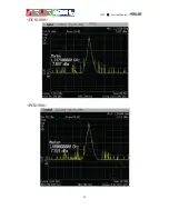
Страница 51: ...GTC Service Manual 51 華 華碩 碩電 電腦 腦 DCS1800 PCS1900 ...
Страница 53: ...GTC Service Manual 53 華 華碩 碩電 電腦 腦 DCS1800 PCS1900 ...
Страница 55: ...GTC Service Manual 55 華 華碩 碩電 電腦 腦 DCS1800 PCS1900 ...
Страница 57: ...GTC Service Manual 57 華 華碩 碩電 電腦 腦 DCS1800 PCS1900 ...
Страница 58: ...GTC Service Manual 58 華 華碩 碩電 電腦 腦 3 4 3 GSM Rx debug The flow chart of GSM Rx debug is shown below ...
Страница 61: ...GTC Service Manual 61 華 華碩 碩電 電腦 腦 GSM1800 GSM1900 ...
Страница 63: ...GTC Service Manual 63 華 華碩 碩電 電腦 腦 GSM1800 GSM1900 ...
Страница 65: ...GTC Service Manual 65 華 華碩 碩電 電腦 腦 ...
Страница 66: ...GTC Service Manual 66 華 華碩 碩電 電腦 腦 WCDMA test points ...
Страница 67: ...GTC Service Manual 67 華 華碩 碩電 電腦 腦 3 5 2 WCDMA Tx debug The flow chart of WCDMA Tx debug is shown below ...
Страница 68: ...GTC Service Manual 68 華 華碩 碩電 電腦 腦 The purpose of Tx debug process is to find out where the problem is on ...
Страница 75: ...GTC Service Manual 75 華 華碩 碩電 電腦 腦 3 5 3 WCDMA Rx debug The flow chart of WCDMA Rx debug is shown below ...
Страница 81: ...GTC Service Manual 81 華 華碩 碩電 電腦 腦 Bluetooth and WLAN test points ...
Страница 87: ...GTC Service Manual 87 華 華碩 碩電 電腦 腦 ...
Страница 88: ...GTC Service Manual 88 華 華碩 碩電 電腦 腦 GPS test points ...
Страница 89: ...GTC Service Manual 89 華 華碩 碩電 電腦 腦 3 7 2 GPS debug The flow charts of GPS debug are shown below ...
Страница 90: ...GTC Service Manual 90 華 華碩 碩電 電腦 腦 ...
Страница 91: ...GTC Service Manual 91 華 華碩 碩電 電腦 腦 ...
Страница 92: ...GTC Service Manual 92 華 華碩 碩電 電腦 腦 ...
Страница 110: ...GTC Service Manual 110 華 華碩 碩電 電腦 腦 voltage supplies and clocks Step4 Press Close GPS to disable GPS test mode ...
Страница 113: ...GTC Service Manual 113 華 華碩 碩電 電腦 腦 5 GPS Debug Tool Operation SiRFDemo Step1 Execute SiRFDemo on GM2 Step2 Press ok ...
Страница 114: ...GTC Service Manual 114 華 華碩 碩電 電腦 腦 Step3 Choose GSW3 and then press ok Step4 Choose GPS parameters like below ...
Страница 117: ...GTC Service Manual 117 華 華碩 碩電 電腦 腦 Step9 Press Exit ...