


18
ASUS P2B-L/P2B-S/P2B-LS User’s Manual
System Memory
III. INST
ALLA
TION
III. INSTALLATION
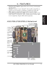
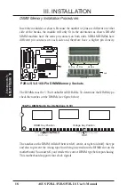
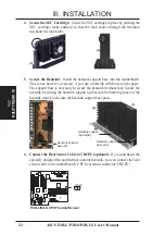
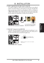
DIMM Memory Installation Procedures:
Insert the module(s) as shown. Because the number of pins are different on either
side of the breaks, the module will only fit in the orientation as shown. DRAM
SIMM modules have the same pin contacts on both sides. SDRAM DIMMs have
different pin contacts on each side and therefore have a higher pin density.
R
Lock
P2B-L/S/LS 168-Pin DIMM Memory Sockets
(FRONT)
88 Pins
60 Pins
20 Pins
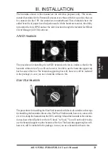
The DIMMs must be 3.3Volt unbuffered SDRAMs. To determine the DIMM type,
check the notches on the DIMMs (see figure below).
168-Pin DIMM Notch Key Definitions (3.3V)
DRAM Key Position
Voltage Key Position
Unbuffered
RFU
Buffered
Reserved
3.3V
5.0V
The notches on the DIMM will shift between left, center, or right to identify the type
and also to prevent the wrong type from being inserted into the DIMM slot on the
motherboard. You must tell your retailer the correct DIMM type before purchasing.
This motherboard supports four clock signals.
Содержание P2B-L
Страница 8: ......
Страница 16: ...16 ASUS P2B L P2B S P2B LS User s Manual This page was intentionally left blank ...
Страница 32: ......
Страница 46: ......
Страница 78: ...78 ASUS P2B L P2B S P2B LS User s Manual This page was intentionally left blank ...
Страница 87: ...ASUS P2B L P2B S P2B LS User s Manual 87 This page was intentionally left blank ...
Страница 88: ...88 ASUS P2B L P2B S P2B LS User s Manual This page was intentionally left blank ...


